|
|
 iter iter |
|
 Ace Ace Posts: 512
Time Online: 309 days 1 hours 7 minutes
|
Richard, thanks. I had the idea I shouldn't glue it, and I appreciate the confirmation.
Cy, no connection. They actually beat me to register that domain in 1997--while I was thinking if I want a .com or a .org, both got registered :=)
Iter means "journey," or "path" in Latin, the English word "iteration" is derived from it. It's been my handle ever since I needed one to log into computers. I even had a logo for it :=) This one must be 15 years old.
Ari.
|
|
|
|
|
|
| iter |
|
Ace
Posts: 512
Time Online: 309 days 1 hours 7 minutes
|
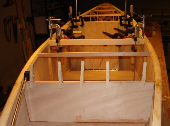
Hours today: 4.5
Running total: 278.5
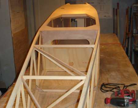
Cut out and glued in cockpit corner reinforcements, engine compartment rear wall and associated crossmember; attached seat and seatback; glued fuel tank shelf reinforcement member.
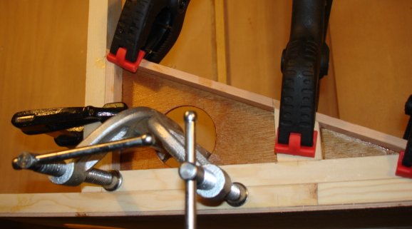
I figured the corner reinforcements were mostly gussets, and their middle portions didn't do much, so I drilled holes in them. Didn't save much weight, but made me feel good. As an added benefit, holes made it easier to clamp the pieces together. I coated the gussets in epoxy seeing as I will not be able to varnish them once I glue in the upper deck.
Ari.
|
|
|
|
|
|
| George Sychrovsky |
|
Guest User |
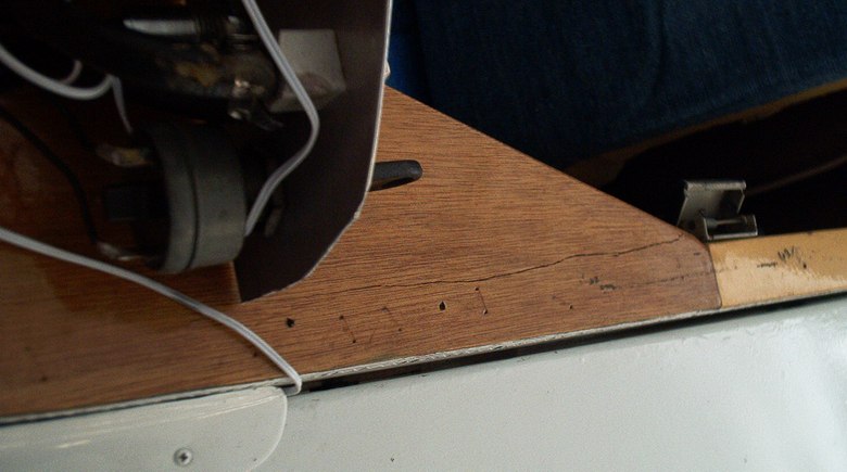
Cutting that hole is a bad idea, that gusset is subjected to very high loads when twist forces are applied to the fuselage like when hitting a pothole with one wheel. This gusset is one of the first things to break. Like this.
|
|
 Logged Logged |
|
|
|
|
| iter |
|
Ace
Posts: 512
Time Online: 309 days 1 hours 7 minutes
|
George, thank you for pointing out my mistake. Do you think I should glue another piece of plywood on top (or the bottom rather) of this gusset? Or perhaps I should add gussets to the front of the crossmember? Or maybe a piece of triangular stock inside the cavity? Or maybe all of these?
Ari.
|
|
|
|
|
|
| beckmore |
|
Fledgling Member  Posts: 2
Time Online: 2 hours 35 minutes
|
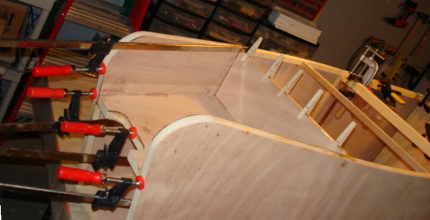
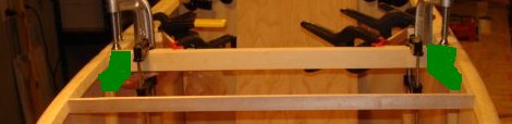
It seams to me that in both picture above, the grain direction of the plywood was wrong, they shoud be vertical to those members.
am I right? like this
|
|
|
|
|
|
| beckmore |
|
Fledgling Member Posts: 2
Time Online: 2 hours 35 minutes
|
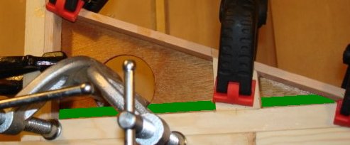
and I find it alot easier to leave the side panel of and put them on the last step, it make it more accessable, espectialy when doing the engine mount base, like this I can make sure they are good fit
|
|
|
|
|
|
| beckmore |
|
Fledgling Member Posts: 2
Time Online: 2 hours 35 minutes
|
and the side can be sanded very flat to make sure the side panel will bond well.
|
|
|
|
|
|
| iter |
|
Ace
Posts: 512
Time Online: 309 days 1 hours 7 minutes
|
Wane, excellent point about the grain direction, I made sure to use transverse grain in this piece. Also, your advice about leaving off side plywood is good, if late. A number of people have already made the same suggestion in this thread in the past,, but after I'd glued them in.
Ari. |
|
|
|
|
|
| iter |
|
Ace
Posts: 512
Time Online: 309 days 1 hours 7 minutes
|
Hours today: 6.5
Running total: 285
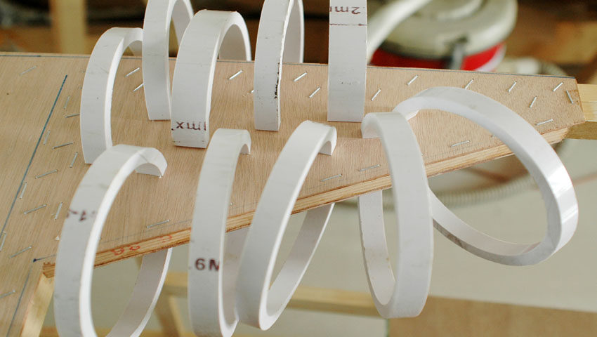
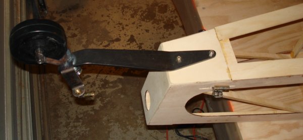
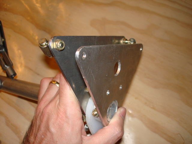
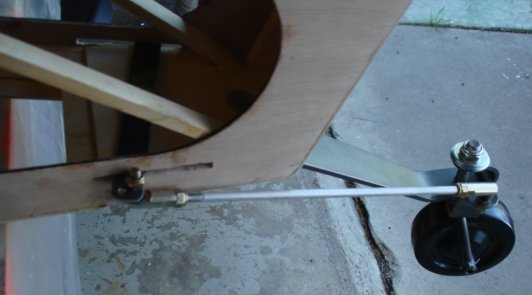
Made tailwheel steering bar; installed tailwheel; made fairleads for tailwheel cables; replaced wrong-sized aileron yoke with an excellent part Dennis made for me from my DXFs; routed the back end of the top plywood deck to shape and glued it in place.
I don't have a photo of the top deck today because the fuselage is sittin upside down while glue cures and there isn't much to see.
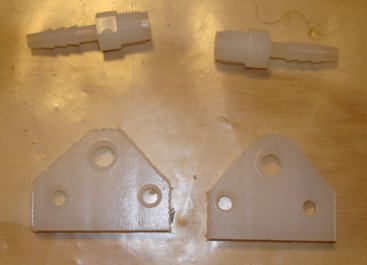
I found the two plastic parts (pictured above my fairleads) among the kit hardware. Are these the "cable guides" the plans speak of? I found no other use for them, but I'd appreciate it if anyone can confirm this is what I should use them for.
Ari.
|
|
|
|
|
|
| Randy lewis |
|
 Ace AcePosts: 965
Time Online: 21 days 18 hours 20 minutes
|
Ari, I used nylon toilet seat bolts and nuts for the plastic guide. I just drilled a hole through the center then cut to length. |
|
|
|
|
|
| djohn |
|
 Ace AcePosts: 648
Time Online: 24 days 19 hours 31 minutes
|
Quoted Text
Are these the "cable guides" the plans speak of?
The "hose barb" fittings you are referring to are in fact the cable guides. Dennis |
|
|
|
|
|
| iter |
|
Ace
Posts: 512
Time Online: 309 days 1 hours 7 minutes
|
Thanks Dennis. And thanks again for the yoke. I remember you mentioned you made the holes slightly undersized. It wasn't too much work to enlarge them, but if you're going to make similar parts for yourself I recommend against it. I filed the holes larger by hand, and their finish is nowhere as good as what you produced. Yours were exceptionally smooth. Thank you again, and let me know if there's anything I can do for you in turn.
Ari. |
|
|
|
|
|
| djohn |
|
Ace
Posts: 648
Time Online: 24 days 19 hours 31 minutes
|
Thanks for all of the kind words Ari. That was the first metal part I produced on the CNC router. there is a little deflection in the Router mechanism which means you don't get what you program. I will just program them a little larger next time, I knew how difficult it would be to enlargen them by hand which is why I warned you in advance about them.
On the "anything I can do in return", I would be pleased as punch to see you complete the plane-thats all.
Thanks
Dennis |
|
|
|
|
|
| Charlie Harris |
|
 Ace AcePosts: 922
Time Online: 23 days 31 minutes
|
Iter: I'm always late, but a hi-speed Dremal with a fine grinder will produce a smoot hole. also a lot of guys do not have anything to turn a 5/8th or 1in. hole. I You can find a Spade bit that has the short points on the side you can go through the .125 aluminum. Just bore 1/2 way then turn over to the other side. try it on a scrap peice. it works. Someone has just got to get a tip page started. Charlie |
|
|
|
|
|
| Charlie Harris |
|
Ace
Posts: 922
Time Online: 23 days 31 minutes
|
Randy: toilet seat bolts? You must have come up with that idea like the toilet tank washers for the fuel filler neck gasket. Charlie |
|
|
|
|
|
| iter |
|
Ace
Posts: 512
Time Online: 309 days 1 hours 7 minutes
|
Oh, it wasn't difficult, I just hated putting scratch marks on this beautiful surface. And you did warn me that the openings were a couple of thousands undersize, so there was no surprise.
Charlie--I think you're right about a tips page. A wiki perhaps?
Ari. |
|
|
|
|
|
| Larryg |
|
Fledgling Member Posts: 15
Time Online: 2 days 5 hours 59 minutes
|
Hi,
Just found your log. Well done. Where did you get the ordinates for the wing rib? I screwed up my drawing and been looking for the ordinates since.
Larry |
|
|
|
|
|
| iter |
|
Ace
Posts: 512
Time Online: 309 days 1 hours 7 minutes
|
Hours today: 5
Running total: 290
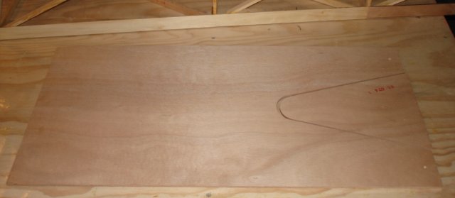
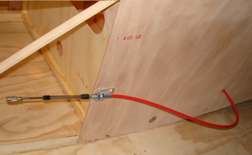
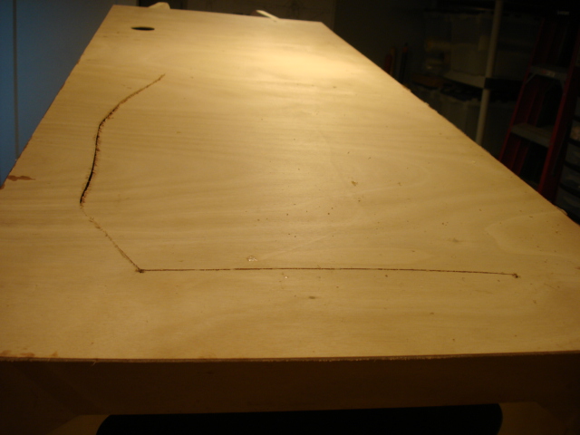
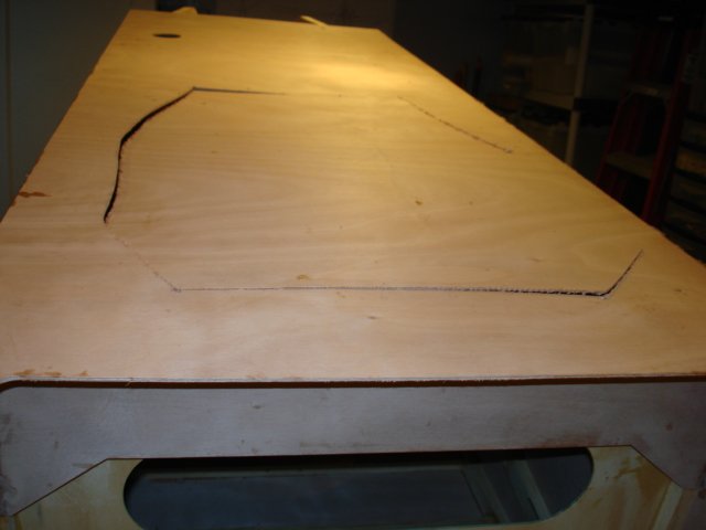
Routed floorboard cutout; cut a thread into and installed tailwheel pushrod; cut cockpit opening & cut top deck to shape; installed control stick and aileron teleflex cables; installed fuel tank.
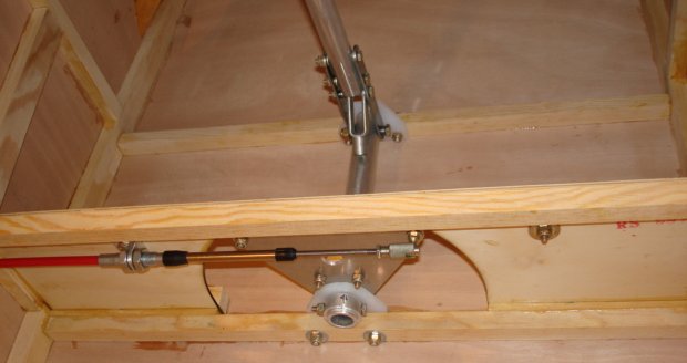
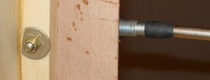
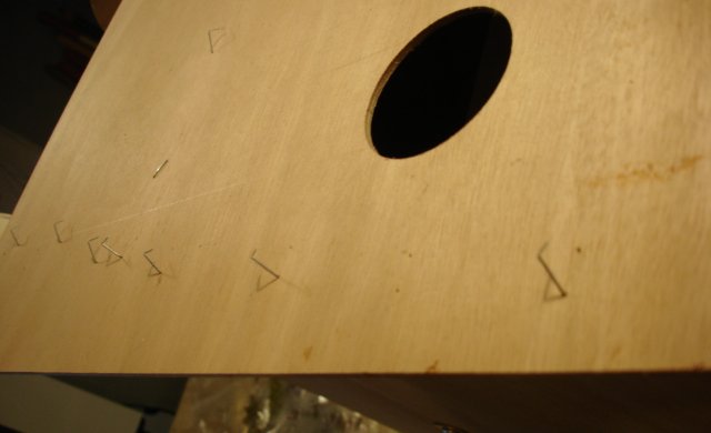
I know I'll have to take many of these fittings out, perhaps more than once. I wanted to see how they all fit together. I was surprised, for instance, at how much the red teleflexes stick out. Am I supposed to have this huge loop hanging out in the slipstream? Also, there wasn't enough room on the upright for a 970-3 washer, so I cut mine. Is this typical or even acceptable (see photo)?
Ari.
|
|
|
|
|
|
| iter |
|
Ace
Posts: 512
Time Online: 309 days 1 hours 7 minutes
|
I used fiberglass-reinforced strapping tape for staples again. This time I used two layers of it, and it worked really well. In the few places where the tape didn't pull staples clear out of the plywood, it at least pulled one side which made it easy to pull the rest.
|
|
|
|
|
|
| iter |
|
Ace
Posts: 512
Time Online: 309 days 1 hours 7 minutes
|
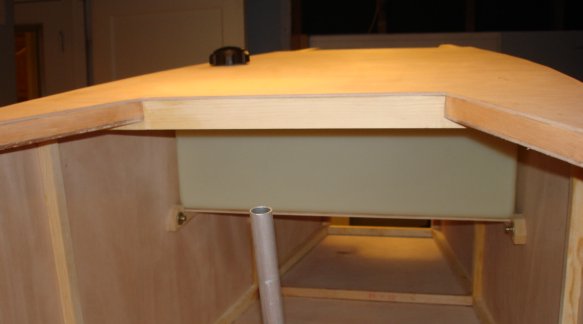
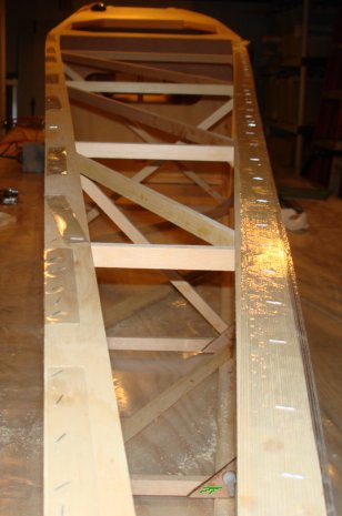
I used a scroll saw to cut the cockpit opening. I'd strategically drilled four holes before I glued the top deck in to tell me where to start cutting, and then cut along the perimeter. It felt like opening a tin can.
Ari.
|
|
|
|
|
|
| iter |
|
Ace
Posts: 512
Time Online: 309 days 1 hours 7 minutes
|
Hi,
Just found your log. Well done. Where did you get the ordinates for the wing rib? I screwed up my drawing and been looking for the ordinates since.
Larry
Larry, welcome to the board and thank you for your comments. I traced the original drawing because by the time I got to making DXFs, I'd already built a jig and all my ribs, so I had to make my CAD fit the physical "legacy" parts. If you are starting from scratch, I'd suggest using NACA 4414 which is what the airfoil is supposed to be based on. This thread has some relevant discussion: http://www.lonesomebuzzards.com/cgi-bin/forum/Blah.pl?m-1200899724/s-0/Ari. |
|
|
|
|
|
| Larryg |
|
Fledgling Member Posts: 15
Time Online: 2 days 5 hours 59 minutes
|
Hi Ari,
I looked at the 4414. The rear spar would be shallower then the current airfoil.
I owned the 1100 plans since 2000. I love the plane but not sure of the 2 stroke.
Larry |
|
|
|
|
|
| iter |
|
Ace
Posts: 512
Time Online: 309 days 1 hours 7 minutes
|
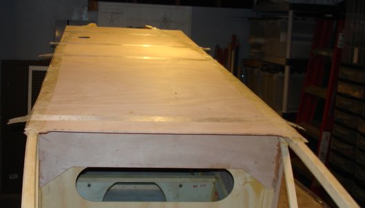
Hours today: 1.5
Running total: 291.5
Cut and glued top plywood strips; installed rudder cable fairleads & cable guides.
Ari.
|
|
|
|
|
|
| iter |
|
Ace
Posts: 512
Time Online: 309 days 1 hours 7 minutes
|
Larry, don't know about the spar. I'm sure if you called JDT and gave them your plans number and explained that you damaged a drawing, they'd mail you an new one, for a nominal fee at most.
Ari. |
|
|
|
|
|
| Larryg |
|
Fledgling Member Posts: 15
Time Online: 2 days 5 hours 59 minutes
|
Ari,
One of the reason's for the airfoil ordinates is I have a homemade CNC router to cut out the gussets and nose pcs.
I downloaded the dxf file for the airfoil.
What engine are you going to use?
Thanks |
|
|
|
|
|
| iter |
|
Ace
Posts: 512
Time Online: 309 days 1 hours 7 minutes
|
The airfoil is the least-useful part of my drawings, precisely because I had to reverse-engineer it from ribs I'd already made. I'll happy if you find the files useful though.
My plans call for Rotax-447. I have not bought an engine yet.
Ari. |
|
|
|
|
|
| iter |
|
Ace
Posts: 512
Time Online: 309 days 1 hours 7 minutes
|
Hours over the last week and today: 6
Running total: 296
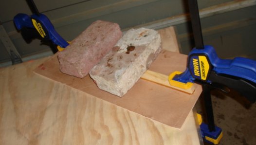
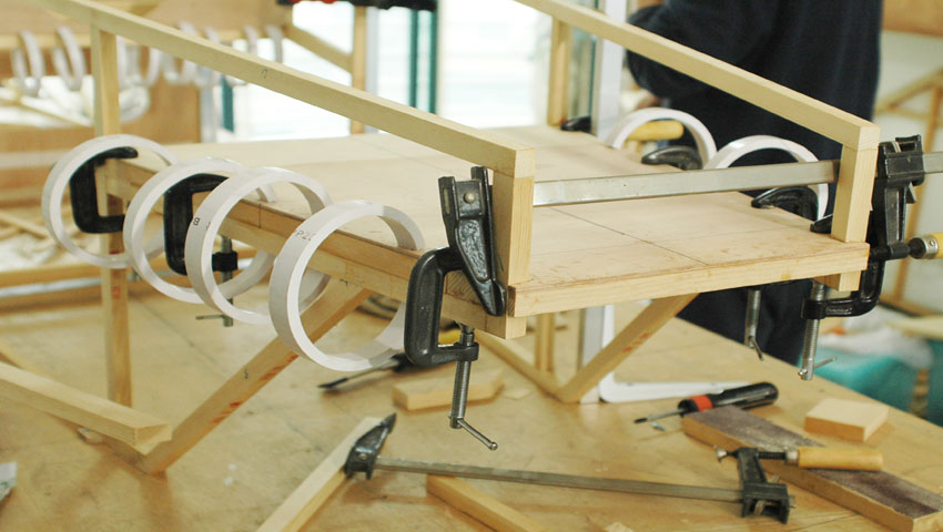
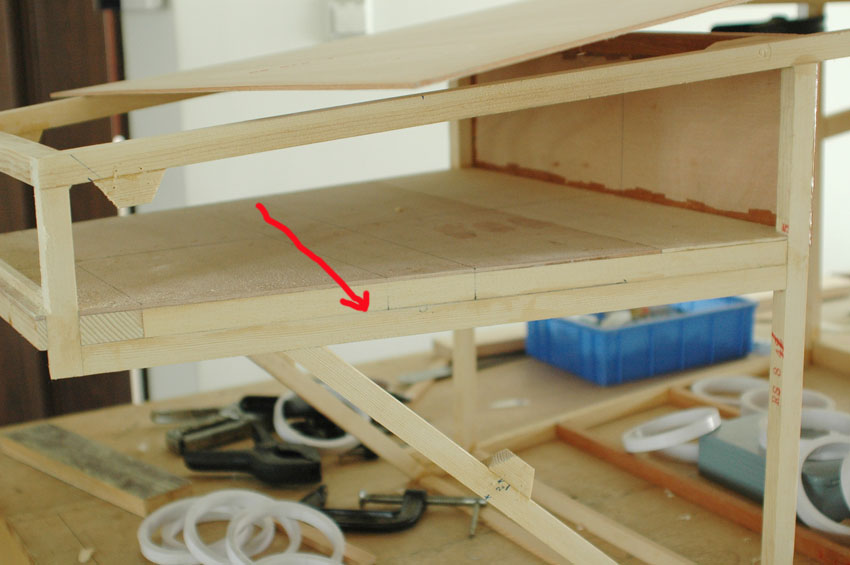
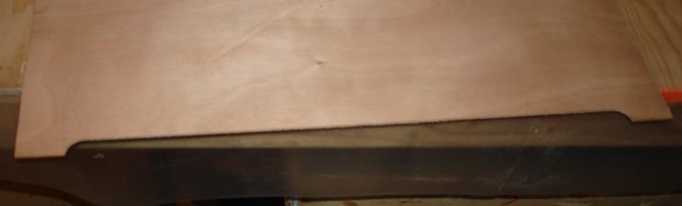
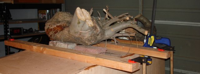
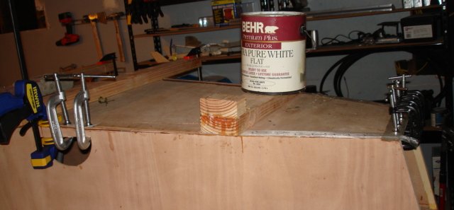
I finished a few odds and ends in the fuselage (a couple of missing gussets, etc.), removed and re-glued the bottom ply and started on the landing gear.
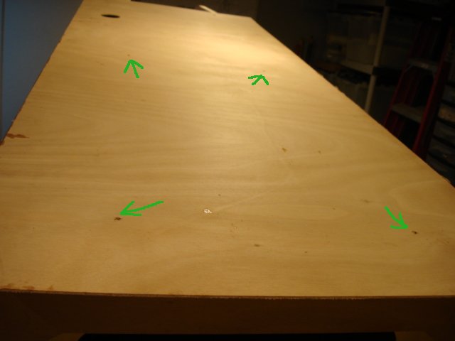
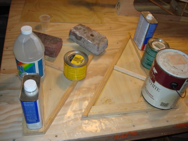
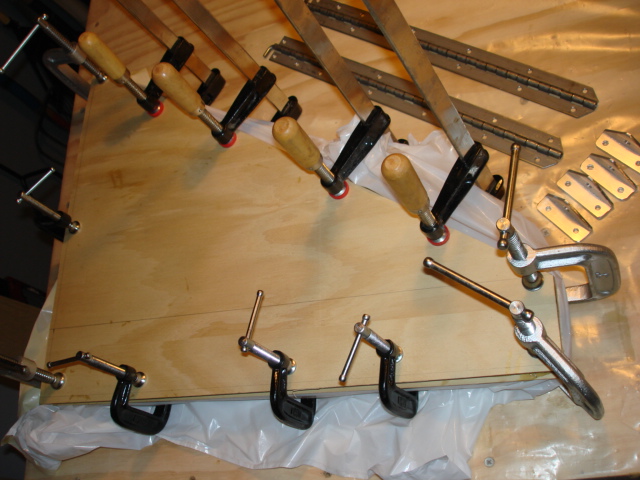
Given the trouble I had last time with the bottom ply, I wanted to make sure I clamped and weighed it down as thoroughly as I could. Don't mind the tree stumps :=)
Ari.
|
|
|
|
|
|
| iter |
|
Ace
Posts: 512
Time Online: 309 days 1 hours 7 minutes
|
Hours today: 5
Running total: 301
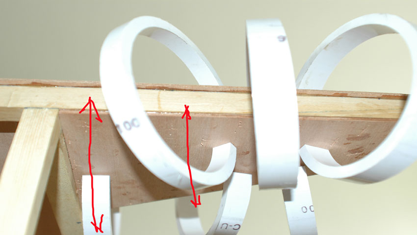
Ran the gear legs through a belt sander, glued their other skins and made some metal hardware for the LG.
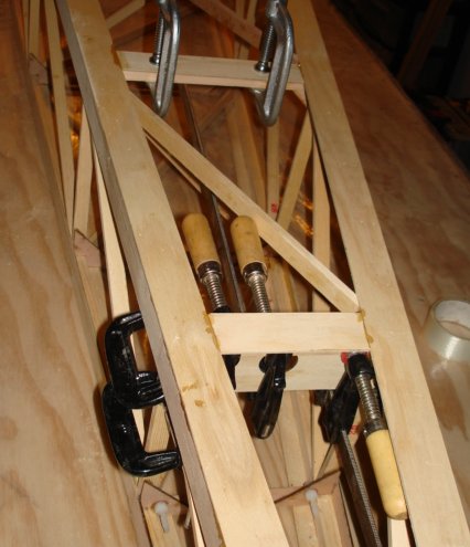
Two gear legs are stacked one on top of the other. Lower one is wrapped in garbage bag for glue separation.
I've reached the 300 hour mark. I must be done according to JDT literature!
Ari.
|
|
|
|
|
|
| Pilotpeat |
|
 Ace AcePosts: 498
Time Online: 13 days 4 hours 21 minutes
|
Ari- I recently broke 300 hours on my Tandem Airbike and I had 30 ribs done, all four spars and the metal fittings for the wings (aileron, strut & wing attach). Other than a couple of other small parts that is pretty much all I had.
Pete |
|
|
|
|
|
| Pilotpeat |
|
Ace
Posts: 498
Time Online: 13 days 4 hours 21 minutes
|
Don't mind the tree stumps :=)
Ari.
Those tree stumps look like they are probably part of a honey-do list...  |
|
|
|
|
|
|