|
|
 Gene Gene |
| September 24, 2007, 11:51pm |
|
Ace
Posts: 283
Time Online: 9 days 1 hours 4 minutes
|
Harold,
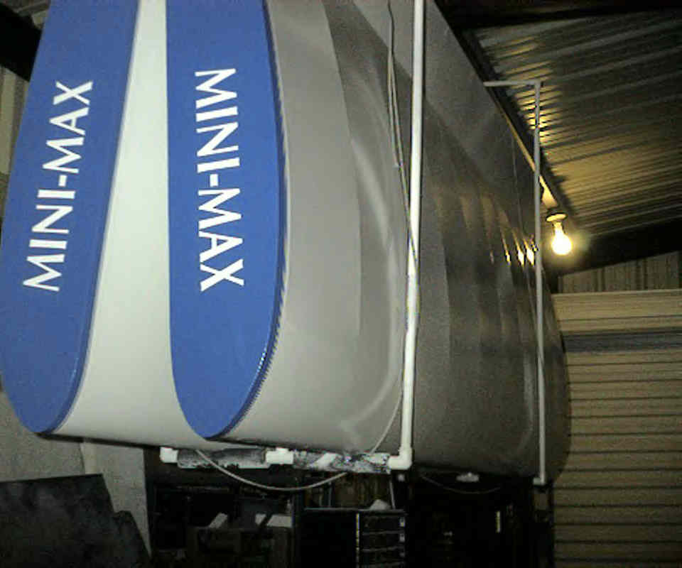
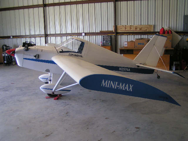
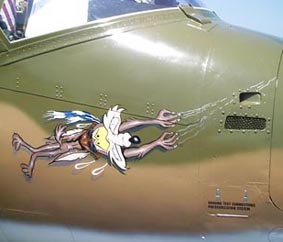
I hope these two pictures give you an even better idea of what I'm suggesting. Have a SUPER day....!
Gene
|
|
|
|
|
|
| iter |
| September 25, 2007, 12:06am |
|
 Ace AcePosts: 512
Time Online: 309 days 1 hours 7 minutes
|
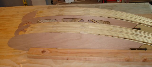
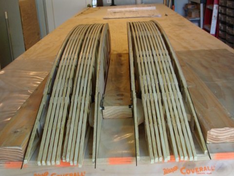
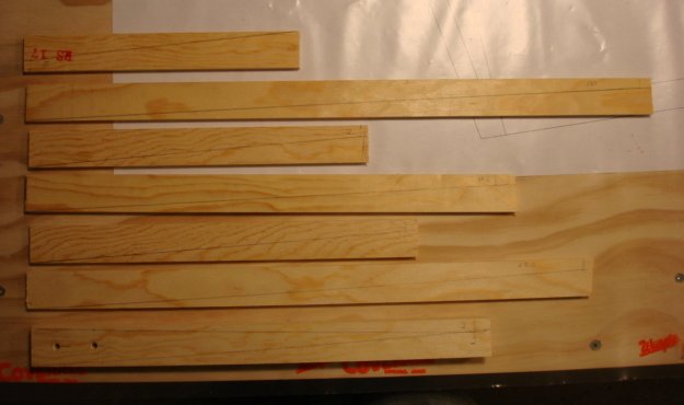
Hard to believe, but I think I've finished the ribs. I spent 95 89 hours and 2 months doing that. Here are my two wings :=)
Thanks for sharing your views on TE curl and remedies. I'll follow this advice when I get to cutting the ailerons off.
Ari.
|
|
|
|
|
|
| 10 |
| September 25, 2007, 12:09am |
|
Guest User |
Thanks Gene, Thats excactly what I thought, Sweet! I wish I would of thought of that in the first place. Shouldn't add too much weight either (my plane is E-LSA certified so it really doesn't matter now). I plan on moving my plane from Texas to Georgia next year and doing some major, major changes. Could I do this mod in the process? Harold
P.S. one of the major changes I have in mind is running a PVC pipe to route all the wiring from the engine fire wall straight to the instrument panel instead of through the firewall, over the gas tank to the panel. Ever hear of that? |
|
 Logged Logged |
|
|
|
|
| Gene |
| September 25, 2007, 1:44am |
|
Ace
Posts: 283
Time Online: 9 days 1 hours 4 minutes
|
Harold,
I don't know why you couldn't go back and do this mod at a later time. As I see it, the only problem you will have is making sure you have enough clearance between the trailing edge of the wing and the aileron. A big part of the required clearance is the straightness of the wing and aileron.
I have never heard of using a PVC pipe for running wires through the firewall, but I suppose it could be done. I'd like to see some pictures after you're done.
Gene |
|
|
|
|
|
| iter |
| September 25, 2007, 3:54am |
|
Ace
Posts: 512
Time Online: 309 days 1 hours 7 minutes
|
Now that I'm done with ribs, I want to start on the fuselage, so that visitors will see something that looks like an airplane. The question comes up about storing ribs. They don't fit into any boxes I have, and some of them (the ones with hinges) are odd shapes and can damage other ribs if I store them in a stack. I'd appreciate any input you guys have on this.
Ari. |
|
|
|
|
|
| Pilotpeat |
| September 25, 2007, 8:16am |
|
 Ace AcePosts: 498
Time Online: 13 days 4 hours 21 minutes
|
Hey, nice job on those ribs. I think I'm closer to 3 months and 150 hours and I'm not quite to where you are with your ribs. I still have to make and install the plywood sheets for the end ribs, finish up my aileron brackets and a couple other small things. I did finish installing all of my gussets last night though. I promised my wife I would take her out to Outback for "ribs" when I got my "ribs" done.  Looks like it might happen in the next week or two. On storing finished ribs, a lot of pictures I've seen has them hanging off of a wall on two hooks. The hooks or dowels need to be longer than the stack of ribs is tall and you just set the ribs on them with the dowel or hook under the top capstrip between the diagonals. I'm sure someone else had a picture. I haven't made a place to hang mine up quite yet but I will be soon. Pete |
|
|
|
|
|
| Randy lewis |
| September 25, 2007, 11:48pm |
|
 Ace AcePosts: 965
Time Online: 21 days 18 hours 20 minutes
|
Ari,
The wings might be easier to store while you work on the fuse as opposed to the other way around. You can hang them from the ceiling above the garage door, at least I could, giving you more room. |
|
|
|
|
|
| 10 |
| September 26, 2007, 12:00am |
|
Guest User |
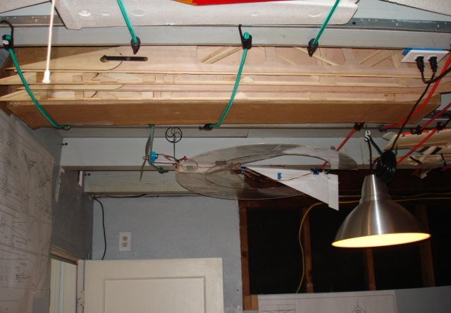
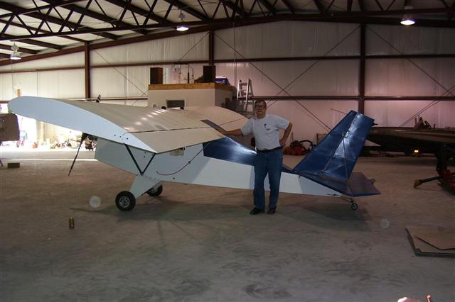
Ari, when you finish your wings, they can take up a lot of space. I made a simple PVC hanger for mine and stored them vertically. You could possible make something similar and hang them horizontally from the ceiling. The picture is from an old digital camera, but you can see how it worked. It was easy to slide the wings in and out of the holders. Might be trickier horizontally or almost impossible to do. I don't know. My workshop was 30X30 so it was easier to do it this way. Harold
|
|
| Logged |
|
|
|
|
| Charlie Harris |
| September 27, 2007, 4:37pm |
|
 Ace AcePosts: 922
Time Online: 23 days 31 minutes
|
I always thought you should put them behind the couch in the Den, but my wife did'nt like it too much. Charlie |
|
|
|
|
|
| iter |
| September 28, 2007, 6:12am |
|
Ace
Posts: 512
Time Online: 309 days 1 hours 7 minutes
|
Hours today: 3
Running total: 107.5
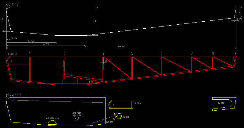
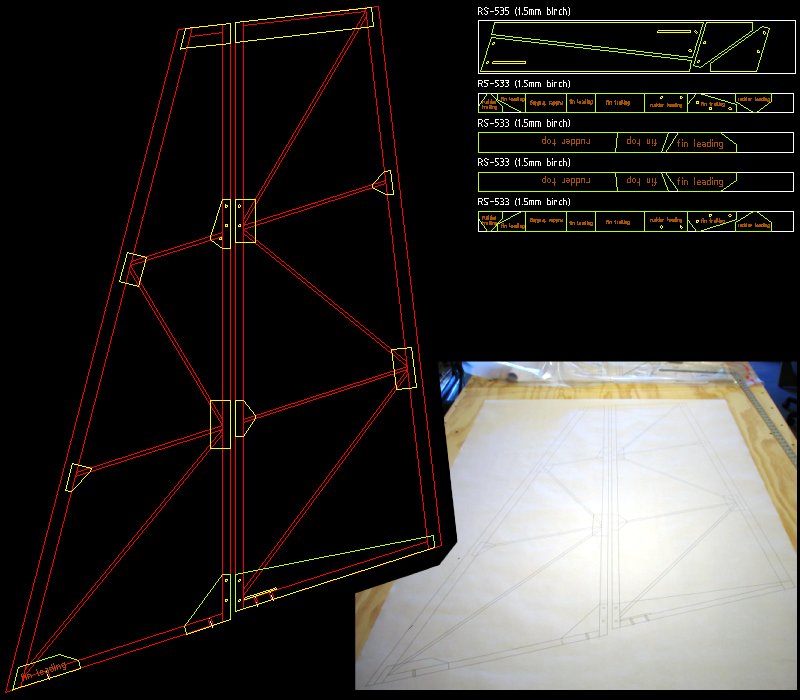
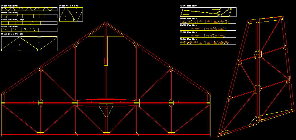
Thanks for storage ideas. I like the two hooks idea. While I'm contemplating rib storage, I started CAD work for the fuselage. I've already drawn full-size paper plans for fuse and the tail feathers, but I decided it was worth my time to redo these in CAD. The main reason is that I'm planning to laser- or CNC-cut the plywood and if I'm doing the plywood pieces I might as well do the whole thing to be sure the frame lines up with the plywood. An added bonus is that I can easily see angles between members which should be handy when I set the miter to cut them. This DXF file reproduces dwg 1"fuselage side view."
Speaking of paper plans, I forgot all about them when I summed my hours. The correct figure is 89 hours to build the ribs.
Ari.
|
|
|
|
|
|
| Charlie Harris |
| September 28, 2007, 11:19am |
|
Ace
Posts: 922
Time Online: 23 days 31 minutes
|
Gotta count it all, building, cutting, sourceing, studying. it's all for the plane injoyment. Charlie |
|
|
|
|
|
| iter |
| September 30, 2007, 8:13pm |
|
Ace
Posts: 512
Time Online: 309 days 1 hours 7 minutes
|
Hours today: 2
Running total: 109.5
I found that my finished ribs fit into the box JDT shipped the wood to me, except the 4 end ribs which are too long. I had a midair with one of my R/C models recently, so space opened up on the ceiling.
I spent a couple more hours drawing DXFs for various parts of the fuselage when it hit me that if I start building the fuselage now, I'll lock myself into a particular kind of engine, and I haven't made that decision yet. So it is possible that I'll start on some other part next, not the fuse.
Ari.
|
|
|
|
|
|
| iter |
|
Ace
Posts: 512
Time Online: 309 days 1 hours 7 minutes
|
Hours today: 3.5
Running total: 113
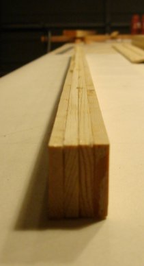
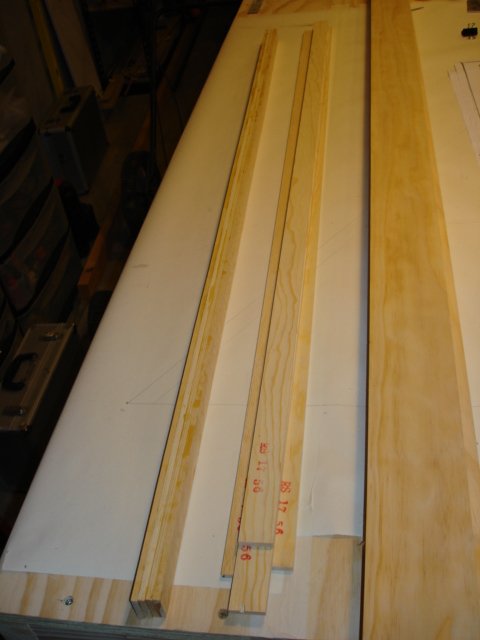
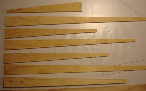
I decided to wait with the fuselage and build the tail next. I started laminating RS-17 leading edges for fin and elevator and cutting aluminum parts.
Ari.
|
|
|
|
|
|
| iter |
|
Ace
Posts: 512
Time Online: 309 days 1 hours 7 minutes
|
Hours today: 5
Running total: 118
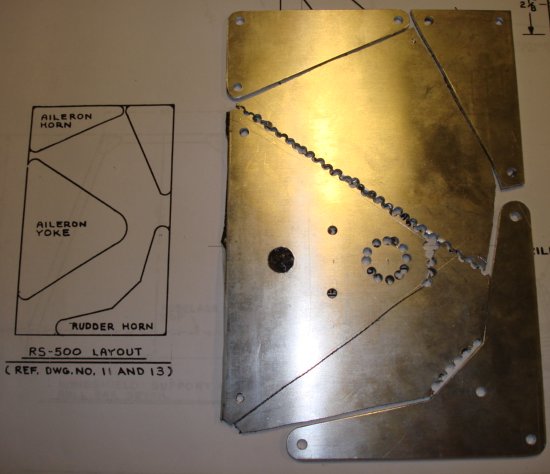
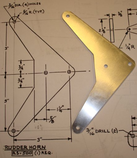
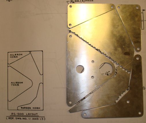
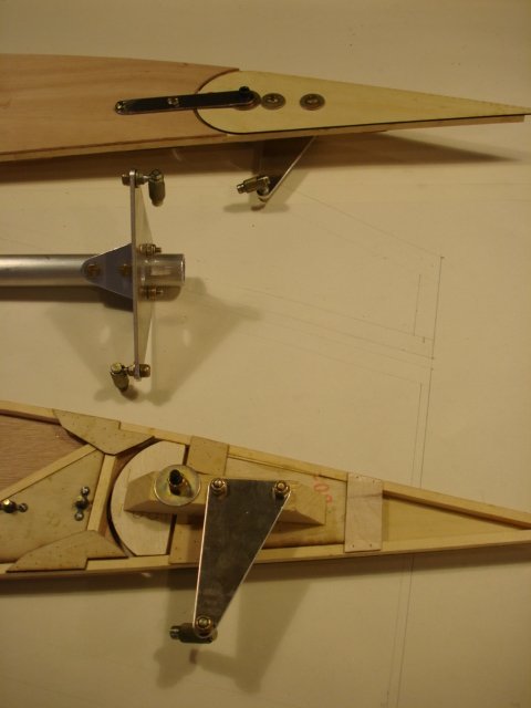
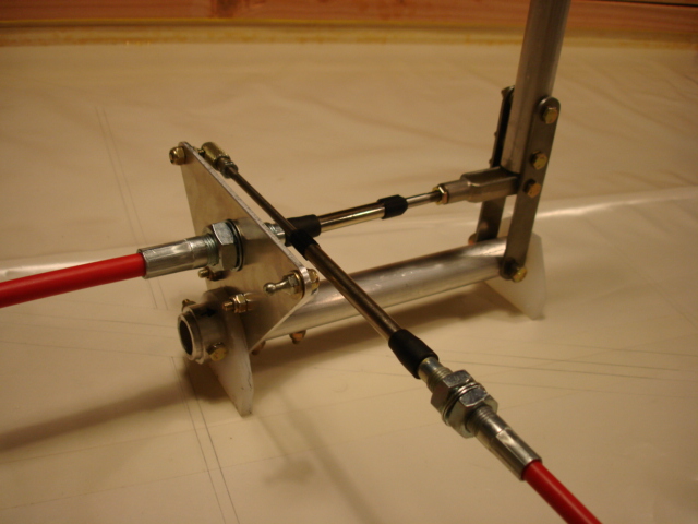
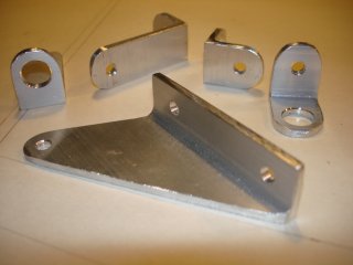
I finished the RS-500 aluminum parts today, and decided to do some more metal work. I wanted to connect the parts I'd made to something, so I made more parts. I now have a finished control stick assembly, the only thing missing is the plastic brackets that mount it to the airframe. The RS-701bearing brackets that hold the stick are the same parts that hold the ailerons. I was amazed how much easier it was to make these compared to the first batch, how much better they came out and how much faster!
Ari.
|
|
|
|
|
|
| skyblazer |
|
Ace
Posts: 213
Time Online: 29 days 11 hours 48 minutes
|
Ari:
Looks like your going to have a nice neat plane when finished, keep on with with the work and PICS of progress..
Dwight (AKA Skyblazer) |
|
|
|
|
|
| iter |
|
Ace
Posts: 512
Time Online: 309 days 1 hours 7 minutes
|
Thanks Dwight! Encouragement like this keeps a builder going.
Ari. |
|
|
|
|
|
| iter |
|
Ace
Posts: 512
Time Online: 309 days 1 hours 7 minutes
|
Hours today: 7
Running total: 125
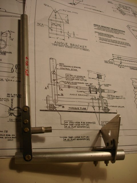
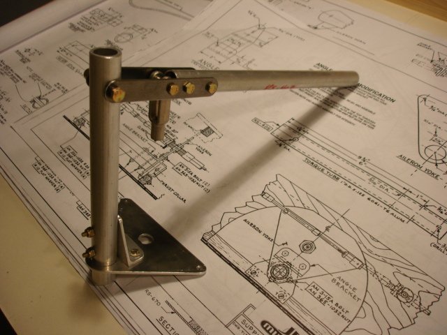
Finished the stick assembly, including plastic support bearings and thrust collar; installed aileron control horns, made elevator control horn and sundry aluminum fittings for Teleflex cables.
More aluminum shaping today. I think I have most if not all of the aileron and elevator control systems finished. There is nowhere to install them yet, of course, but I think I'm done making fittings for them.
Ari.
|
|
|
|
|
|
| iter |
|
Ace
Posts: 512
Time Online: 309 days 1 hours 7 minutes
|
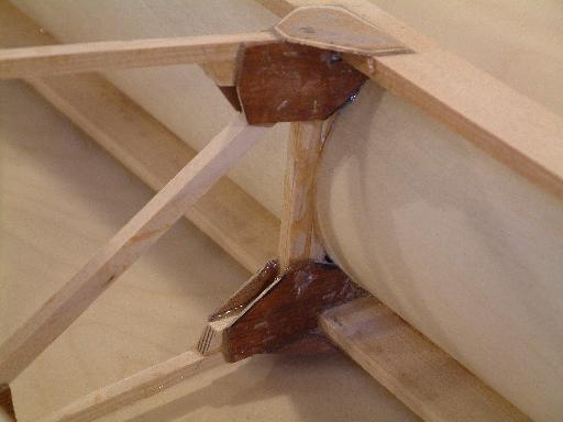
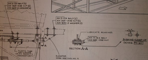
There are two problems I ended up with today. One is that I can't find any mention of how to connect the elevator horn. I assume there is a bolt and perhaps a bushing involved, but I see no mention of it in the plans. Any suggestions?
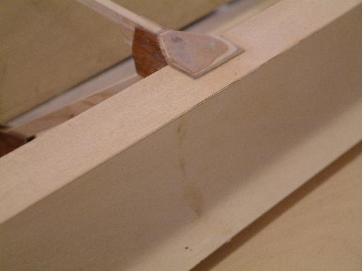
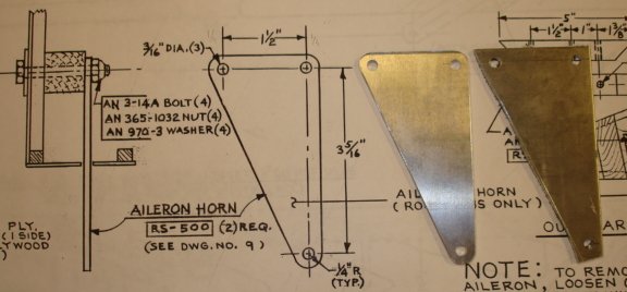
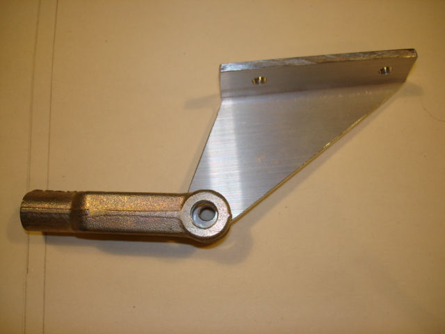
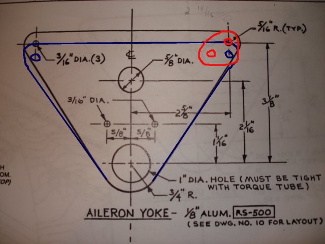
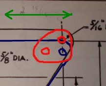
The other is that I made the aileron yoke the wrong shape--5/16" shorter than the plans (blue line). This causes the aileron Teleflexes to bind on the elevator one at fairly small stick deflections and reduces effective aileron travel available. And I was so proud of my aluminum work :=) As I see it, I could make a new yoke (where do you buy a small piece of aluminum, and what type of aluminum is it?) or I could add little triangles made out of RS-500 scraps (red line) and use the one I made. Suggestions welcome.
Ari.
|
|
|
|
|
|
| djohn |
|
 Ace AcePosts: 648
Time Online: 24 days 19 hours 31 minutes
|
Hi Ari, You have really done a great job to date. Don't cheat now. We all make boo boo's and the stock you have cut too short is relatively cheap. My plans call RS500 1/8" 6061 T6. I just looked at Mcmaster Carr's site, a piece of it 12" x 12" is $26 plus shipping. It can be had much cheaper depending on your local sources. There may be a supply house near you that will sell you a "drop" for way cheaper. IMO this is a part you don't want to compromise on. The way you have planned on modifying it it would require one of the "patch plates" on each side of the yoke with a spacer in the middle, then you're rod end fittings will be too short etc...
Sometimes you can find raw material real cheap on ebay and sometimes you also can get a mtl cert with it if you require that.
I have seen steel tubing used for the elevator horn. The tube is just the right size to slide into the clevis and when the bolt is tight the tubing is held stationary in relation to the horn and swivels on the inside of the clevis end. The inside of the tube will barely clear the 10-32 (an3) bolt diameter, and cut the ends very square to keep them from binding in the clevis. Do not let anything move on the bolt diameter, all of the movement must be in relation to the steel tubing and the clevis with a little grease.
Hope this makes sense
Dennis |
|
|
|
|
|
| iter |
|
Ace
Posts: 512
Time Online: 309 days 1 hours 7 minutes
|
Dennis, thanks for your kind words and advice. I hear what you're saying about not compromising. I cut these pieces by hand (SawDushShop doesn't allow metal cutting) and had to spend a lot of time fitting them--not all holes matched, etc. Making a new one means restarting all that... Btw, why do you think I'd need a 3-layer sandwich with "patch plates?" I was going to just use one triangle. The only forces on this part are in the direction of the green arrow. Is there something that is trying to bend the yoke, or is there another reason you'd need the extra thickness?
Re the elevator horn. Is the setup you describe the same as is used on the other side, where the clevis connects to the stick through an RS-600 bushing?
Ari.
|
|
|
|
|
|
| djohn |
|
Ace
Posts: 648
Time Online: 24 days 19 hours 31 minutes
|
Ari, I am not an expert by any means and there are a lot more qualified people on the board to comment on the specifics, I think the patch will create side loads on the yoke which will induce slight twisting of the yoke and possible fatigue of the patches or yoke over time. there would also be three times the hardware for this connection which is just more stuff to check and possibly service. Any deviation in the mounting of a teleflex cable in my opinion is adding risk to your aircraft. Any engineers or fabricators want to step in here, I may be being too precautionary.
I am going to try to cut a similar part on my CNC router at work. The equipment reseller assures me that if I use high speed machining parameters it will cut non-ferrous metals with no problems. If this is the case I might be able to carve one out for you.
Elevator horn is similar to the teleflex cable attachment on the elevator axis of the stick where the bushing is bolted solid and the clevis moves on it.
Dennis |
|
|
|
|
|
| iter |
|
Ace
Posts: 512
Time Online: 309 days 1 hours 7 minutes
|
Dennis, that is a very generous offer and will be most deeply appreciated. I still have a lot of time before I'll actually need the control stick assembly.
Thank you for the elevator horn description. After days of looking for it in the plans, I found it and it was exactly as you described.
Ari.
|
|
|
|
|
|
| iter |
|
Ace
Posts: 512
Time Online: 309 days 1 hours 7 minutes
|
Hours yesterday: 3
Running total: 128
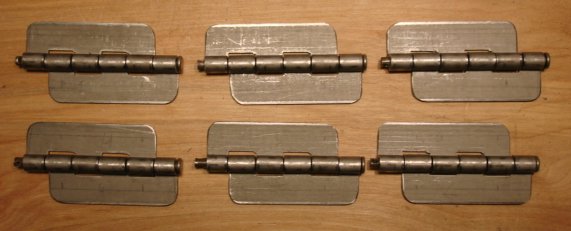
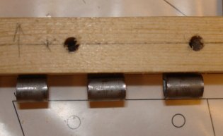
I made hinges for rudder and elevator. I decided I wanted them installed before I assembled the tail surfaces as a single RS is much easier to maneuver around a drill press than a whole elevator for instance. I cut some extra pieces off the hinges because they weren't connected to anything that bears any load. I saved a tiny bit of weight (1.3oz) and ended up with shorter slots in trailing edges. I left of drilling the hinges until after I have slots they fit into so I could meet that the exact clearances specified in the plans. I drilled the wood first, then cut slots, then inserted the hinges and drilled them through existing holes in the wood.
Ari.
|
|
|
|
|
|
| iter |
|
Ace
Posts: 512
Time Online: 309 days 1 hours 7 minutes
|
Hours today: 8
Running total: 136
I finished the CAD for vertical tail and had it printed. The tail is at this odd angle so if would fit on a 36" roll of paper in one piece. For $13.25 including tax, I have a full-size drawing to work with and a guarantee that the gussets I laser-cut will fit what I build. I didn't have time to cut the gussets today, hopefully tomorrow.
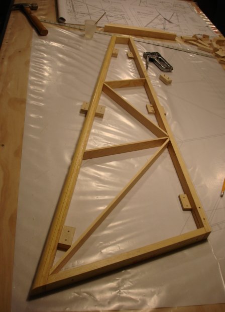
I did rout the laminated leading edges, fit rudder hinges and glued up the fin. No gussets today, but it should hold OK until I glue them in.
Ari.
|
|
|
|
|
|
| iter |
|
Ace
Posts: 512
Time Online: 309 days 1 hours 7 minutes
|
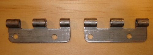
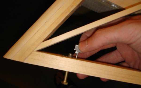
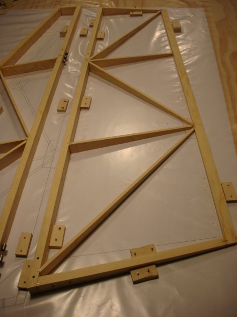
BTW, here's what the hinges ended up like. These are both from the rudder side, I can't touch the fin until it's dry.
Ari.
|
|
|
|
|
|
| 10 |
|
Guest User |
Quoted Text
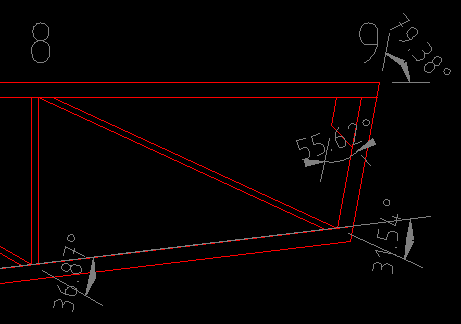
The tail is at this odd angle
I've posted a lot of pictures on this board and no one has noticed that I didn't have that "odd angle" on my tail. The top front of the vertical tail has been lowered by about 2 1/2 inches to be parallel with the bottom of the tail. I just think it gives a sleeker look. That's the only change in original design my plane has. Harold
|
|
| Logged |
|
|
|
|
| iter |
|
Ace
Posts: 512
Time Online: 309 days 1 hours 7 minutes
|
Hours today: 4
Running total: 140
That's a nifty airplane Harold, whichever way you slant the tail! I'm surprised nobody picked up on this modification you made, usually people here are quite keen to point out what they think is a deviation from plans :=)
I had a bad day with the laser today, so I only have about half the gussets I need for the tail. I did cut the fin ribs though. Oh, and where the plans say install blind nuts before installing this member in the fin, they mean it. I wasted an hour trying to screw them in today after the fin was dry.
Ari.
|
|
|
|
|
|
| iter |
|
Ace
Posts: 512
Time Online: 309 days 1 hours 7 minutes
|
Hours yesterday & today: 4
Running total: 144
Finished DXF for horizontal stabilizer.
|
|
|
|
|
|
| iter |
|
Ace
Posts: 512
Time Online: 309 days 1 hours 7 minutes
|
Hours tonight: 2
Running total: 146
Laid up the rudder. I'm still missing some of the gussets--I should have them early next week.
|
|
|
|
|
|
| iter |
|
Ace
Posts: 512
Time Online: 309 days 1 hours 7 minutes
|
Hours today: 3
Running total: 149
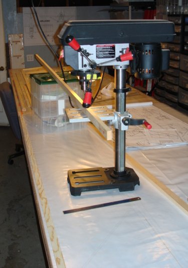
I had full-size plans printed for the horizontal tail and started working on it. Tonight I drilled the spars for hinges. It's awkward maneuvering 90" pieces of stock around my garage, and there was no way to drill them where my drill press normally lives. I had to move it to the worktable temporarily and use some plastic boxes to support the other end of the piece.
Ari.
|
|
|
|
|
|
|