|
|
 iter iter |
|
 Ace Ace Posts: 512
Time Online: 309 days 1 hours 7 minutes
|
Hours today: 11
Running total: 160
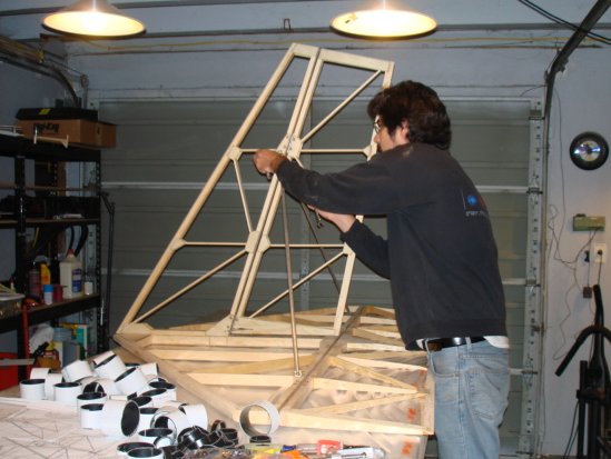
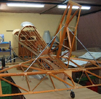
I finally cut all the gussets for tail surfaces and started putting them in place. I also laid up the elevator. I love the PVC pipe clamps. I had a piece of black sewer pipe from when I moved the washer around, and I bought some 3" white pipe, 10' for $4, enough to build three airplanes simultaneously :=) Only problem I found was that they tend to slide off the tapered trailing edge (actually, they pull the gussets, and the gussets slide off, wet epoxy is a good lubricant). I had to use staples on the TE. Maybe if I glue the gussets one side at a time, they won't slide as freely with the clamp grabbing on to dry wood on the other side.
Ari.
|
|
|
|
|
|
| iter |
|
Ace
Posts: 512
Time Online: 309 days 1 hours 7 minutes
|
I guess I misjudged the clamping pressure and one of the gussets, on the top of the rudder, didn't stick quite right. Because there is /some/ epoxy between the gusset and the wood, it is not possible to bend the gusset all the way to where it should be even if I managed to get some glue under it. Any suggestions about what I could do to fix this?
Ari.
|
|
|
|
|
|
| Ricardo |
|
 Videos in UTube: ral1951 AcePosts: 2,772
Time Online: 75 days 23 hours 15 minutes
|
Iter:
IMO, I think that using staples is the best way to ensure a good tight.
It provides an adecuate and even pressure on all the gluing surfaces.
It is fun and fast when pulling them out with the right tool; also a pleasure to see a really good bond.
Ricardo |
|
|
|
|
|
| Charlie Harris |
| October 16, 2007, 11:54pm |
|
 Ace AcePosts: 922
Time Online: 23 days 31 minutes
|
Iter: Just Heat it with a heat gun like a model gun and it will come right of with no damage. then clean up and glue it again. You may be able to take it loose just part of the way then bend it and get glue under it. Charlie |
|
|
|
|
|
| flybob13 |
|
 Ace AcePosts: 222
Time Online: 5 days 20 hours 43 minutes
|
Ricardo, what do you use as a staple puller? Never thought of it as fun. Bob |
|
|
|
|
|
| iter |
|
Ace
Posts: 512
Time Online: 309 days 1 hours 7 minutes
|
Charlie, thanks for the tip! I'll do just that. I wonder if a hair dryer would work?
Ricardo, what is that magic tool you speak of? Like Bob, I haven't been able to find a tool that makes pulling staples "fun." The best I've come up with is a pair of end (or top) cutting pliers.
Ari. |
|
|
|
|
|
| Ricardo |
|
Videos in UTube: ral1951 AcePosts: 2,772
Time Online: 75 days 23 hours 15 minutes
|
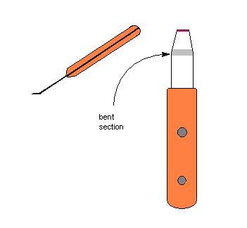
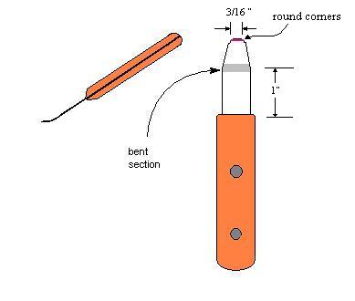
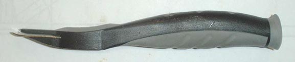
About the tool
Get a good short old knife, I used those with wood handle to cut meat, the small knife.
Make a 30 degree bent about 3/8" from the tip. From the bent to the handle knife is about 1". Make the tool short and sturdy.
Grind it off only one side at the end. Make tip about 1/4 " wide so it will fit under the staple. You just have to press the tip under the staple just a little bit , press the knive handle down and it will pop out. Is not a one step job. As everything is a matter of practice. It takes about 3 to 4 seconds for each staple, warning wear safety glasses because it may jump up to your eyes.
I'll place a picture of my tool later today when I get to the shop.
|
|
|
|
|
|
| iter |
|
Ace
Posts: 512
Time Online: 309 days 1 hours 7 minutes
|
Hours yesterday and today: 7
Running total: 167
Thanks for the heat gun advice, I used Irene's hair dryer and it worked great. I've already put the gussets back together using staples. There's a lesson here about gussets on curved surfaces but I'll post my thoughts on that in the morning--I'm too tired now.
The status today: fin is done, rudder needs the long bottom gussets, stab frame is drying, elevator frame is dry and has gussets on one side. With a little luck, I'm looking at test-fitting the tail tomorrow.
Ari.
|
|
|
|
|
|
| Ricardo |
|
Videos in UTube: ral1951 AcePosts: 2,772
Time Online: 75 days 23 hours 15 minutes
|
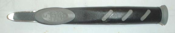
Stapler remover
Sorry didn´t bring my camera to show the tool.
I did the drawing by memory is pretty close only modification will be : tip is 3/18 width and rounded edges.
Ricardo
|
|
|
|
|
|
| iter |
|
Ace
Posts: 512
Time Online: 309 days 1 hours 7 minutes
|
Thanks again for the debonding tip. It worked perfectly and the gusset is back on the way it should be.
Ari.
|
|
|
|
|
|
| iter |
|
Ace
Posts: 512
Time Online: 309 days 1 hours 7 minutes
|
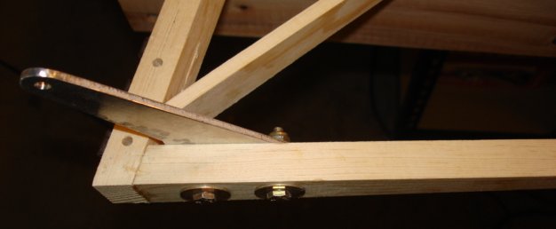
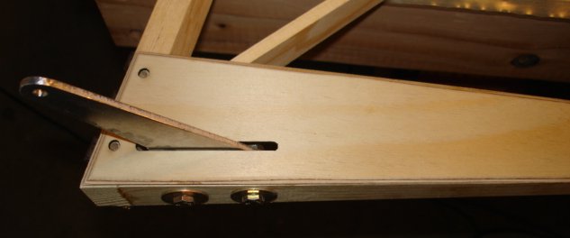
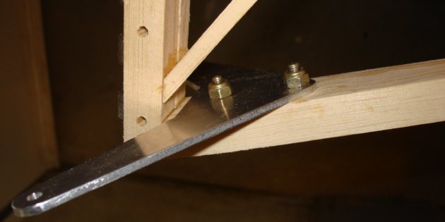
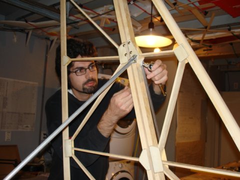
I have a question about the rudder horn for those who've already been here. I bolted it onto the rudder to check how well my gusset will fit, and it occurred to me that with the gussets on, it is next to impossible to get to the nuts. With the covering on, it seems completely impossible, short of an odd-shaped inspection hole. Does this mean that I'll have to put the bolts in first and then apply fabric on top of them?
Ari.
|
|
|
|
|
|
| iter |
| October 19, 2007, 12:35am |
|
Ace
Posts: 512
Time Online: 309 days 1 hours 7 minutes
|
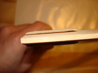
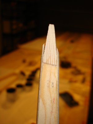
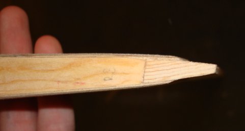
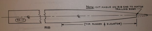
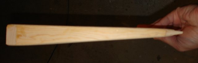
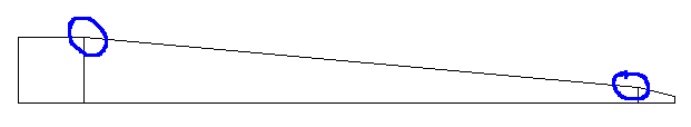
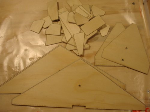
While you guys are thinking about my bolts and covering them, here's the lesson I learned about gussets on curved surfaces.
The plans call for curved ribs on rudder and elevator. I thought this was for aerodynamic reasons and decided to make simpler, tapered ribs. I reasoned the aerodynamic differences would be negligible. This may be so, but what I overlooked was that where standard ribs create a smooth curve with the trailing edge, mine created sharp corners on the trailing edge as well as the spar. (I couldn't get the camera to focus on the right spot, I hope the diagram clarifies what I mean)
These sharp edges make adhesion difficult as they require excessive bending of the plywood. This is why my rudder gussets came apart, and why in the end I needed staples to hold some of the gussets in place. Hope those who haven't built their tails yet can avoid this problem.
Ari.
|
|
|
|
|
|
| bfhowell |
|
Fledgling Member  Posts: 3
Time Online: 9 hours 21 minutes
|
Buy a inexpensive long box end wrench to fit nuts. Heat the end and bend about 45 degrees to fit on nuts in the corner and clear gusset so you can hold it. Grind outside if necessary to fit between the gussets. With rudderhorn off cover side that rudderhorn sticks out. Install rudderhorn and hold nuts with bent wrench. Cover other side. |
|
|
|
|
|
| Kevin Larke 1300Z |
|
Flight Leader  Posts: 140
Time Online: 2 days 11 hours 4 minutes
|
My favorite staple remover came from Office Max. I believe it's made by Stanley-Bostitch. It has a soft rubber handle, metal blade tip, and smooth hard plastic bottom. It's easy to wiggle the blade under the staple wire and pop it out.
Look at your staples. I have some J-21 types that are basically square wire. I think they are Arrow brand. It's harder to get the puller under the staple without marring the wood. I have some with wire that is more round. I think they are Stanley brand. They are easier to remove.
|
|
|
|
|
|
| iter |
|
Ace
Posts: 512
Time Online: 309 days 1 hours 7 minutes
|
With rudderhorn off cover side that rudderhorn sticks out. Install rudderhorn and hold nuts with bent wrench. Cover other side.
J, thanks for the input. The horn sticks out both sides, it's a pull-pull system. Regardless, I don't see any problem installing the gussets over an installed horn. What I'm worried about is that I can't install the horn after I /cover/ the rudder, and so I'll be forced to cover the bolts with fabric. Ari. |
|
|
|
|
|
| iter |
|
Ace
Posts: 512
Time Online: 309 days 1 hours 7 minutes
|
Maybe someone who's already got the rudder covered could post a photo of the horn attach bolts?
Ari. |
|
|
|
|
|
| bfhowell |
|
Fledgling Member Posts: 3
Time Online: 9 hours 21 minutes
|
Would it cause any problems if you added a little flat strip along the bottom drilling out for the bolt heads and washers so the heads of the bolts would be flush? |
|
|
|
|
|
| Pilotpeat |
|
 Ace AcePosts: 498
Time Online: 13 days 4 hours 21 minutes
|
You might also think about using a captive nut like on some of the aileron bearing bracket bolts. You can then just have the nutplates in the rudder, cover it and then install the bolts and rudder horn. The nutplates can be held in with small #4 by 1/4" long stainless PK screws.
I can post a photo of this when I get home if you need.
Pete |
|
|
|
|
|
| iter |
|
Ace
Posts: 512
Time Online: 309 days 1 hours 7 minutes
|
You might also think about using a captive nut like on some of the aileron bearing bracket bolts. You can then just have the nutplates in the rudder, cover it and then install the bolts and rudder horn.
Blind nuts is the first thing I thought of--I was wondering why the plans call for them on the fin but not on the rudder. Then it dawned on me that you'd need the blind nuts installed on the rudder horn, not on the wood. I suppose I could tap the horn and use thicker bolts, but I'm not sure a 1/8" aluminum is strong enough to hold the loads. Ari.
|
|
|
|
|
|
| iter |
|
Ace
Posts: 512
Time Online: 309 days 1 hours 7 minutes
|
Hours yesterday and today: 7
Running total: 174
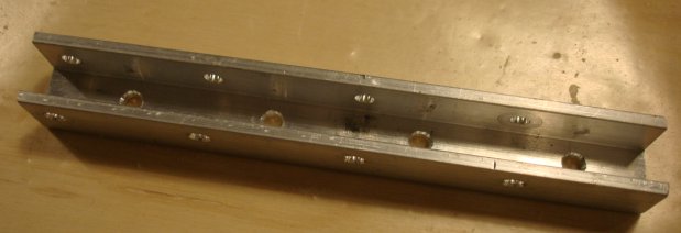
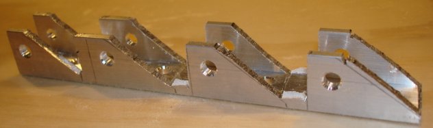
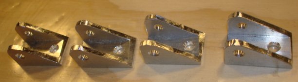
Glued gussets to both sides of the stab and made 4 little aluminum fittings that hold the fin-to-stab bracing tubes.
Incredibly, I used up the entire 10-foot length of 3" pipe I bought. Truly, you cannot have too many clamps. I tried a new technique with aluminum fittings. I drilled and rough-cut them before I cut the piece up into separate pieces. I like this approach. It's easier to clamp large pieces than small, and drilling was certainly more precise this way.
Ari.
|
|
|
|
|
|
| bfhowell |
|
Fledgling Member Posts: 3
Time Online: 9 hours 21 minutes
|
I guess those bolts are 1/4-20 and the load is at a right angle to the bolt. Suppose you made a new horn and drilled with a #8 bit and tap for 80% threads and made a mock-up out of scrap for test and just see how much it will hold. I bet the wood would give away first. |
|
|
|
|
|
| JGlassFNP |
|
 Wing Man  Posts: 56
Time Online: 8 hours 12 minutes
|
Hey guys, new builder here ... 1103R #173 ...
I started on the end of April or so and have completed the tail-frathers, fuselage, gear, and starboard wing ... I have all of the ribs ands spars done for the port wing done.
I mounted the empenage on the fuselage this week and just finished fitting/installing the strut braces and the elevator control cable. My cable positioning does not "center" the stick. It appears as though I'll have to add a 1.5" block to the forward floor cross member and move the control-stick ass'y forward.
I'm getting ready to order a Hirth F-33, 2.5:1 drive, electric start very soon ...prices are going up due to the $ vs Euro. I'm considering a 2-blade, 54" IVo-prop ... can anyone comment on this combo.
Thanks,
Kurt Satter
Industrial Engineering
Louisiana Tech University |
|
|
|
|
|
| iter |
|
Ace
Posts: 512
Time Online: 309 days 1 hours 7 minutes
|
Suppose you made a new horn and [...] made a mock-up out of scrap for test
J, I appreciate the suggestions. I don't want to reinvent the wheel here. I'm curious how people who've already done it done it. Ari. |
|
|
|
|
|
| iter |
|
Ace
Posts: 512
Time Online: 309 days 1 hours 7 minutes
|
Hours today: 1.5
Running total: 175.5
Glued the last remaining gussets on rudder and elevator.
Ari. |
|
|
|
|
|
| iter |
|
Ace
Posts: 512
Time Online: 309 days 1 hours 7 minutes
|
Hours today: 3
Running total: 178.5
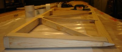
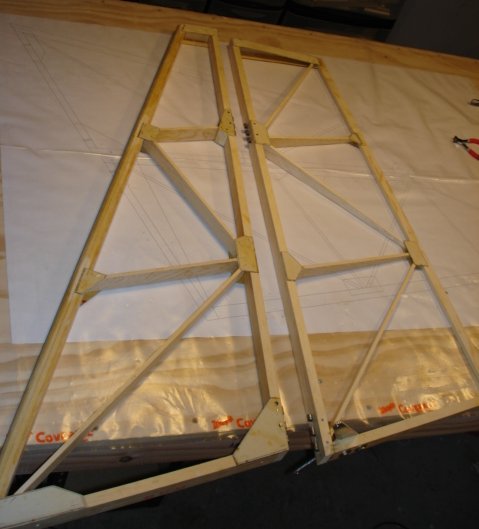
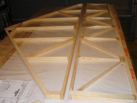
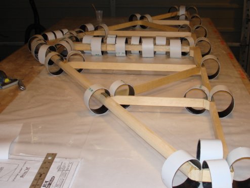
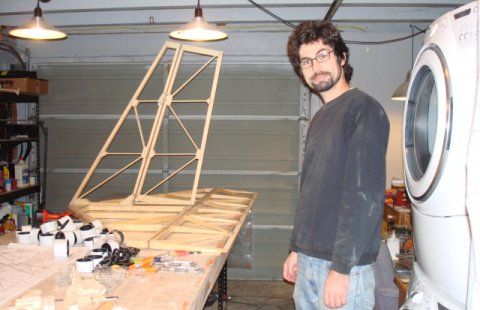
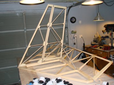
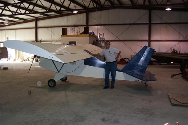
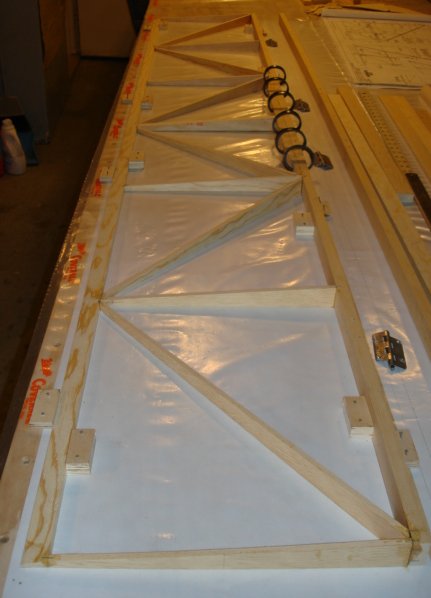
I finished the tail today.
Ari.
|
|
|
|
|
|
| iter |
|
Ace
Posts: 512
Time Online: 309 days 1 hours 7 minutes
|
A few more photos--Irene had a ball with the camera today :=)
|
|
|
|
|
|
| JGlassFNP |
| October 22, 2007, 11:37am |
|
Wing Man Posts: 56
Time Online: 8 hours 12 minutes
|
My plans included a "Light Tail" alternative ... is there a reason you built the one you did?
Kurt |
|
|
|
|
|
| iter |
|
Ace
Posts: 512
Time Online: 309 days 1 hours 7 minutes
|
My plans gave me no alternatives. I've heard about the light tail, what does it look like?
As far as I understand it, the 1030 was designed to stay within Part 103 weight and had the lighter 277 engine up front. This made it impossible to balance with the normal tail, so Ison designed a lighter tail for it. It is also my understanding that the lighter tail comes with a 90 mph Vne restriction as opposed to 100 mph for a regular one. Neither speed is attainable of course except in a steep dive.
I'm very curious about the actual differences between the "regular" and the light tail.
Ari. |
|
|
|
|
|
| iter |
|
Ace
Posts: 512
Time Online: 309 days 1 hours 7 minutes
|
Hours yesterday: 8
Hours today: 5.5
Running total: 192
I spent 3 hours yesterday cleaning my garage after I was done with the tail. Sawdust, shavings, epoxy, bits of RS and plywood--all of it knee-deep--I figured I had to do it at some point. Felt surprisingly good, too.
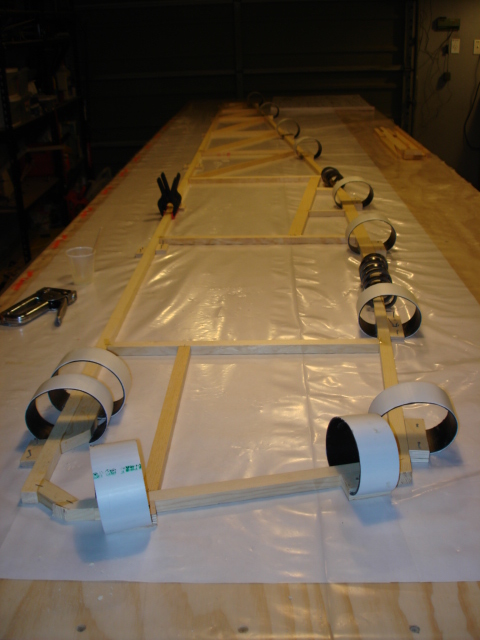
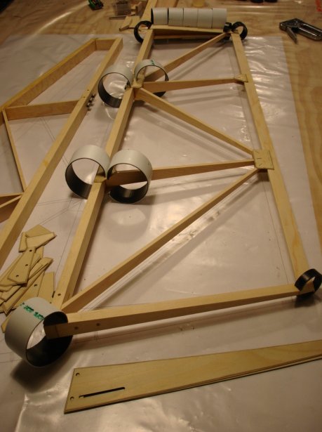
Anyway, I printed out a full-size fuselage drawing and laid up one side of the fuse on it. I also kept drawing more parts to laser- and CNC-cut. I'll post the DXF when I'm done.
Ari.
|
|
|
|
|
|
| iter |
|
Ace
Posts: 512
Time Online: 309 days 1 hours 7 minutes
|
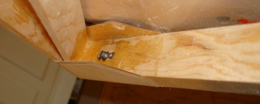
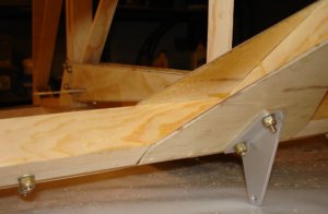
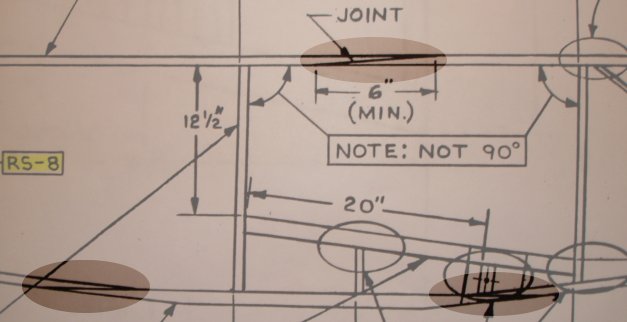
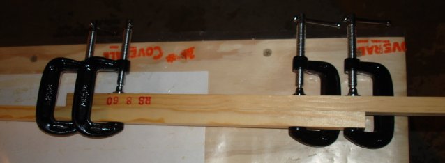
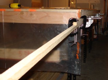
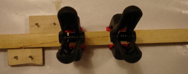
I was worried about cutting the very sharp edges for longeron splices, especially on the top longeron (where it says "joint") because the two parts have to match. I read on this board about a trick I found useful, so I'll post a few pictures of it, or at least of how I understood it.
I clamped the two pieces together using 4 little C-clamps, then clamped the whole assembly to my bench and used a hacksaw to cut them both at the same time. This produces a cut that us not necessarily straight, but matches on both parts. Last photo shows the splices drying in the layup. I'll post a photo tomorrow of how it turned out.
Ari.
|
|
|
|
|
|
|


 Logged