|
|
 beragoobruce beragoobruce |
|
Built an Eros - now I'm flying it! Ace Posts: 1,067
Time Online: 19 days 10 hours 58 minutes
|
Now it's easy to see where to put the wings when I'm rigging!
|
|
|
|
|
|
| pkoszegi |
|
 Ace AcePosts: 1,363
Time Online: 41 days 7 hours 42 minutes
|
Bruce, you always amaze me with these details.
If you are near to install your engine and thinking about your instrument panel, send me a PM . If you are interested I will work out a very special price on the instrument electronics. I need a reference in Australia.
Peter |
|
|
|
|
|
| beragoobruce |
|
Built an Eros - now I'm flying it! AcePosts: 1,067
Time Online: 19 days 10 hours 58 minutes
|
Thanks, Peter, both for your kind words & your offer on the instruments. I have pm'd you.
Bruce
|
|
|
|
|
|
| aeronut |
|
 blue sky and tail winds to everyone AcePosts: 1,560
Time Online: 28 days 22 hours 31 minutes
|
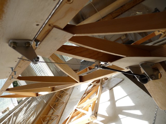
That is really great the way you have done the fairing. I have often wondered about the effect of fairing this area; it has got to be positive and I suspect quit significant. Thank you for the post.  |
| never surrender; never give-up |
|
|
|
|
|
| beragoobruce |
| September 7, 2015, 2:43am |
|
Built an Eros - now I'm flying it! AcePosts: 1,067
Time Online: 19 days 10 hours 58 minutes
|
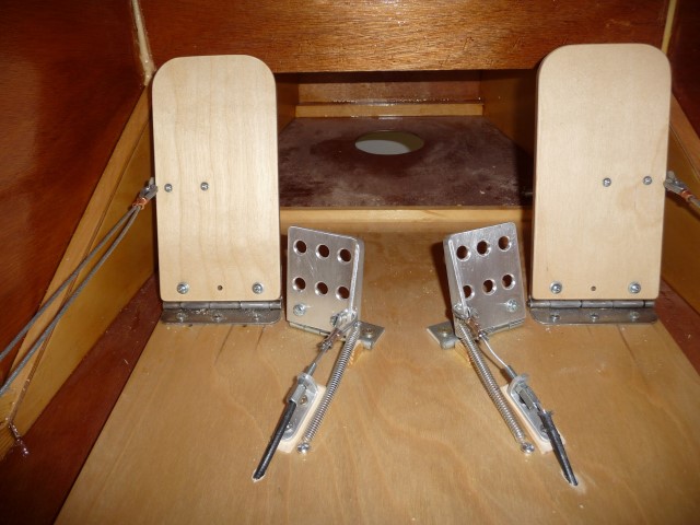
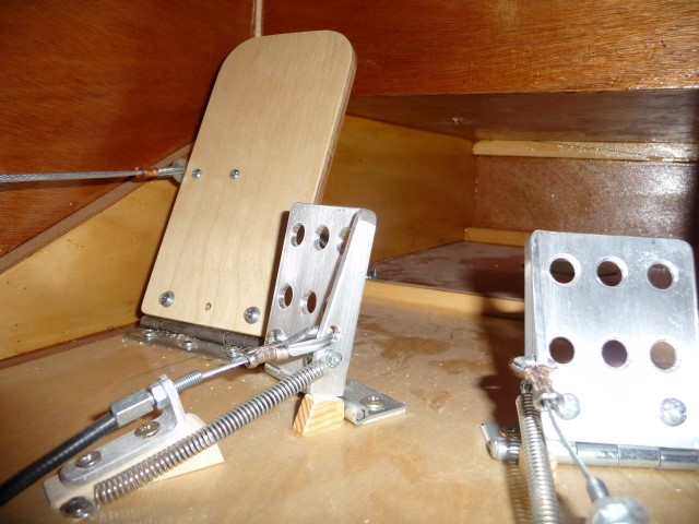
I decided to fit differential brakes, since it seems worthwhile to do a bit extra to acquire a bit of help on low speed taxiing if you're going to fit brakes anyway. And I don't really like the idea of a single brake lever mounted on the stick.
I went for heel brakes over toe brakes, because a) the space is a bit limited above the pedals for a separate brake area and b) heel brakes are easier. I expect to get used to their operation during all my ground handling, & high- & low-speed taxi trials. If not, I'll change them.
I made the pedals from 2.5" x 2.5" x 1/8" angle, with a nice radius root. The hinge was just a heavy duty hardware store item. I decided to terminate the cable at the brake pedal with an eye fitting because it's too hard to reach down there to adjust the cable length, & I have adjustment at the wheel end. I put light springs on to hold the pedals against a wooden stop. I may make an aluminium cover for the cable end as it looks a bit untidy. Or maybe not!
In order to determine the optimum position for the ergonomics of the pedal operation, I made an accurate wooden mockup of the rudder pedals & the brake pedals on a dummy floor. I sat on a box & positioned the rudder pedals as they are in the plane. Then I played around with different placement for the heel brakes. Best for me came out as shown in the pic.
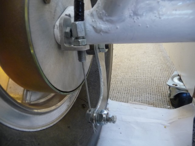
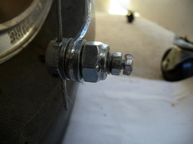
At the brake arm end, I made a fitting from a 10mm s/s bolt. I drilled through the centre & tapped it to take a 4mm bolt. I drilled through the head to allow the brake cable to pass through, and tightened the centre bolt to clamp the cable. I locked it with a plain nut. The 10mm bolt has washers each side of the brake arm, and a nylock nut adjusted to permit rotation but minimum slop.
I fitted an outer cable adjuster to a small angle bracket as per plans.
|
|
 |
|
|
|
|
|
|
| Tom |
| September 7, 2015, 1:30pm |
|
Ace
Posts: 744
Time Online: 16 days 10 hours 21 minutes
|
The wing root fillets can indeed reduce drag substantially. The amount is calculable. See Hoerner's "Fluid Dynamic Drag" for how to calculate it. You need an estimate of the speed of the aircraft and the length of the wing chord and from there the calculations are very simple.
There are two types of drag that this filleting can reduce, but in this particular case where the wings are close to 90 degrees from the fuselage the really important type is called "interference drag". What happens with a "hard" unfilleted inside corner is that the boundary layers of the two surfaces are meeting at an angle to each other. Therefore they "interfere" with each other's flow and "trip" the flow into severe turbulence. The amount of drag at a hard corner like this when calculated out is quite significant. Adding a generous fillet allows each boundary layer to bend toward the other until they are meeting as though they were flow on one surface.
While the calculations given for this are pretty "fuzzy" the answers will be in the right ballpark and will allow some pretty good estimates of improvement in speed if you've precalculated the actual drag in flight. Conversely it can also give a good estimate of reduced fuel consumption.
It is worth mentioning that filleting at the roots of empennage surfaces, strut to surface intersections, landing gear to fuselage intersections, etc can all benefit from fillets to reduce interference drag.
Tom |
|
|
|
|
|
| Ricardo |
| September 7, 2015, 3:31pm |
|
 Videos in UTube: ral1951 AcePosts: 2,772
Time Online: 75 days 23 hours 15 minutes
|
Bruce:
I wonder if your design has enough cable travel to exert enough pressure on the drums.
I have the Azusa brake system hand operated, and is far from perfect. The drum have some little offset to the center axle and it needs quite a travel to tight the brakes. With only hand brakes I can keep the plane stopped at 5000 rpm maximum. At higher rpm it starts rolling.
WIll like to change to hill brakes to get tighter turns on my runway. |
|
|
|
|
|
| beragoobruce |
| September 8, 2015, 8:12am |
|
Built an Eros - now I'm flying it! AcePosts: 1,067
Time Online: 19 days 10 hours 58 minutes
|
Thanks for the input to both Ricardo & TTT.
I will look out for the potential problem you raise, Ricardo. I am expecting to take up the slack by re-adjusting at the brake arm after a bit of bedding in of the brake linings. If there is insufficient travel available at that time, I will either move the cable further up the heel lever, or shorten the brake lever as per TTT's suggestion.
TTT, I made my own fittings because the cable stops I bought were clearly meant for a throttle, and the tiny little screw in them didn't look to be strong enough to take a frightened man standing on the brake pedal.
It is hard to assess the required travel before actually using the system. Similarly, the amount of pedal pressure needed for the brakes to be at all effective (which of course will be affected by the length of the brake arm). So your inputs are appreciated: I'll let you know how it goes in the field.
Bruce |
|
|
|
|
|
| NowraSteve |
|
Wing Man  Posts: 68
Time Online: 3 days 11 hours 56 minutes
|
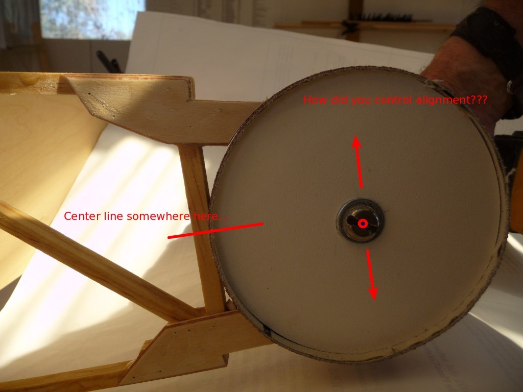
The trickier bit was the "closing web" for the rear spar.
Hi Bruce, Going back a ways, if I may, to this post... Question: How did you control the alignment of the sanding disc relative to the centre target point of the ribs? Particularly how did you ensure that all the ribs were the same? Just careful eyeballing and a steady hand? Did the sanding wheel tend to track to the same centre because the rib gussets were all carefully cut to the same length? Simply stunning build BTW! So please excuse me as I contemplate copying as much as possible  (within my very limited limits). Steve.
|
|
|
|
|
|
| beragoobruce |
|
Built an Eros - now I'm flying it! AcePosts: 1,067
Time Online: 19 days 10 hours 58 minutes
|
Thanks for your kind words, Steve.
To sand the rear spar ribs to fit the closing web, I did this by hand. If you look much earlier in my thread, when I made the gussets located at the rear spar, I modified their profile to form an arc about the pivot point of the aileron hinge.
Then when sanding with the gadget as shown in your quoted pic, the device just automatically centres where it should.
After initial sanding, I strung a chalk line the full length of the rear spar, at several positions around the closing spar area. This showed up high points or out of line areas, which were sanded down.
You need to allow quite a generous clearance between the aileron nose skin & the closing web trailing edge spars, because there will be two thicknesses of Dacron +glue + paint. And to allow for a bit of wing flex in turbulence.
Bruce |
|
|
|
|
|
| lake_harley |
|
Ace
Posts: 1,095
Time Online: 25 days 7 hours 43 minutes
|
Regarding the gap between trailing edges of the wing and the aileron nose skin, I was advised to leave about 3/32" gap when I was to that point in construction. Since the gap varied a slight amount when the aileron was moved through it's range of motion, I checked for that clearance while moving the aileron and checking the clearance. It worked out OK once everything was covered, so I'd say I got good advice. Regarding Dacron Bruce, I did a single layer wrap around the aileron leading edge and did the cloth overlap at the trailing edge....ie: I started the cloth on the top of the aileron trailing edge (about 1" or so), wrapped around the bottom of the aileron, over the top and used a pinked edge then on the underside of the aileron trailing edge to finish it off. That gave a total cloth overlap of about 2". Maybe you were also referring to the cloth wrapped around the top and bottom trailing edges of the wing? I just thought of that possibility as I was about to hit "Post Reply"  Lynn |
|
|
|
|
|
| beragoobruce |
|
Built an Eros - now I'm flying it! AcePosts: 1,067
Time Online: 19 days 10 hours 58 minutes
|
Hi Lynn.
Yes, I meant the underside of the upper & lower trailing edges, plus the cloth wrapped around the leading edge 'nose' of the aileron. I've edited my post to try to make this more clear. Thanks!
Bruce |
|
|
|
|
|
| beragoobruce |
| November 29, 2015, 12:56am |
|
Built an Eros - now I'm flying it! AcePosts: 1,067
Time Online: 19 days 10 hours 58 minutes
|
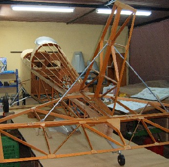
The last few weeks I've been finishing off all the small jobs on my fuselage. This has taken a lot of time, & it's easy to start thinking I'll never get finished. But I have now almost got to the end - I think. I have the engine installed, and the fuselage is rolling on its wheels. So I must be nearly there!
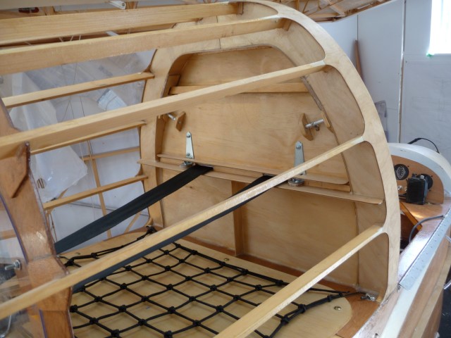
One of the fiddly bits was the baggage bay. It seemed to me there was a lot of empty space behind the main bulkhead (aft end of cockpit), which is close to the c.g. & could therefore be useful for carry bulky, if not heavy, items. I'm thinking sleeping bag, tent, jacket, etc for when I fly away from home. I will need to establish - and placard - the safe weight I can carry when I do my weight & balance.
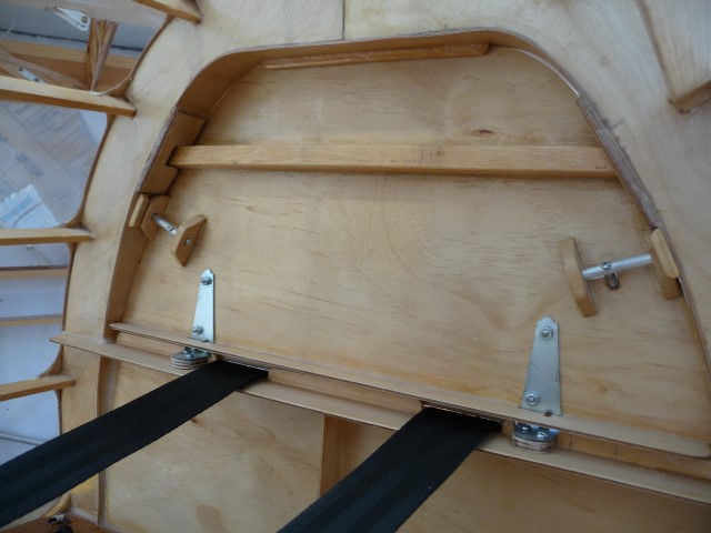
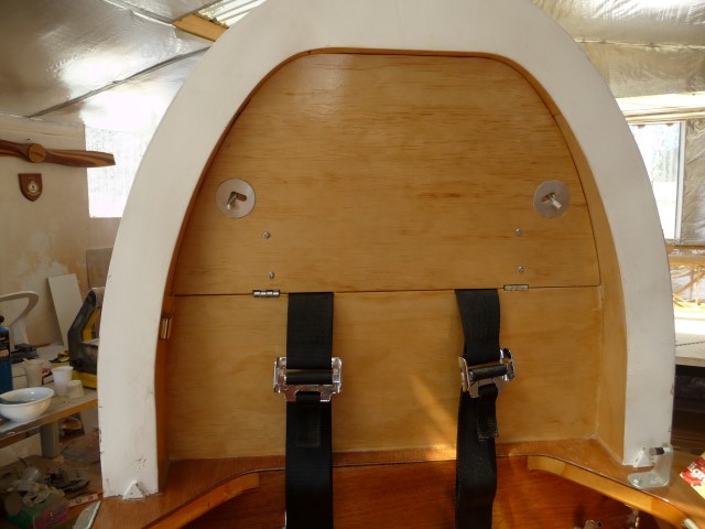
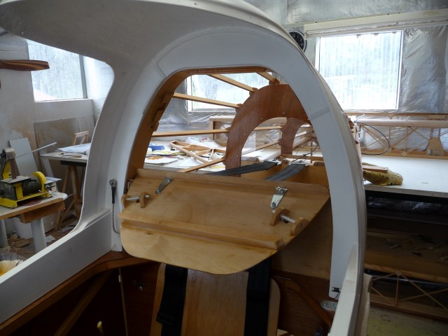
I made a 3mm poplar ply infill for the main frame, the upper portion of which was the access door. I stiffened the two panels with 1" ribs epoxied behind them, & mounted the hinges behind the door to conceal them.
I made a couple of barrel bolts from 1/4" dia aluminium rod to keep the door shut, and glued a bit of RS9 across the area where my head is to provide some whiplash support in case I reverse into something solid at high speed. The forward face of the door will carry a padded headrest in due course. The crosspiece engages in a couple of housings bonded to the rollover hoop sides.
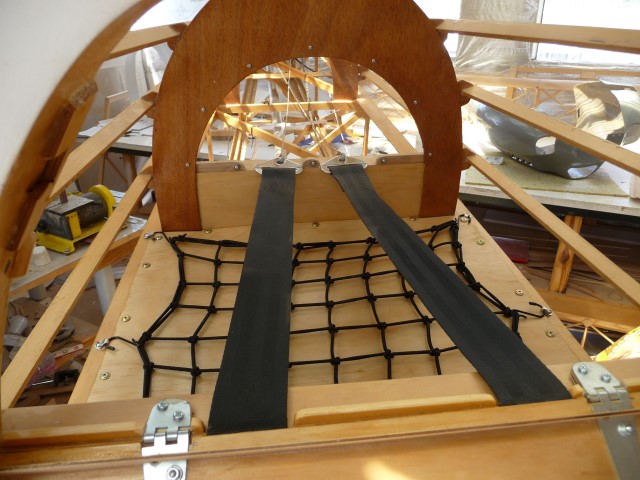
I put in an additional diagonal at the baggage bay floor level, making an 'X' shape support for the floor. The floor itself is 3mm poplar ply. I screwed this in place, so that it is removable. Then I made some small ally clips to provide anchor points for a cargo net. (I have used these cargo nets on my motorbikes, & it is surprising how good they are at holding stuff, even at unfeasibly high road speeds.)
I exited the seatbelt shoulder straps at the height they naturally want to be relative to my shoulders, so the baggage bay bulkhead is not taking any load in a crash. what limited stuff I carry can fit mostly under the belt straps.
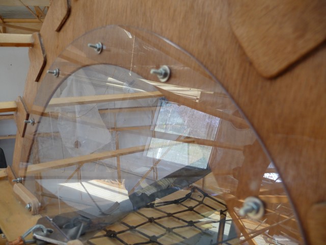
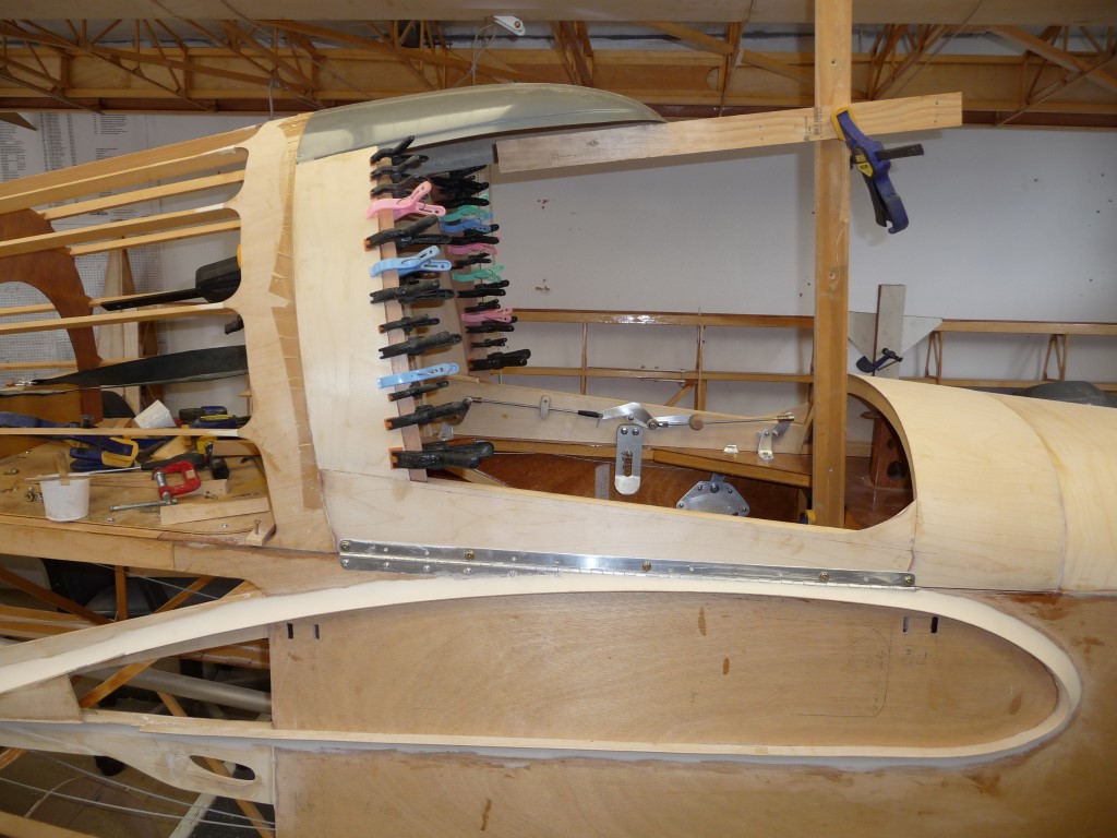
I still wanted to be able to visually inspect the rear fuse, but I didn't want to have a gap under the frame in case baggage came adrift & fell into the rear fuse. So I fitted a Lexan infill to, well, fill in this space. The 3mm bolts in the pic are temporary, I will replace them with button heads when they arrive from Hong Kong.
So here's the pix:
|
|
 |
|
|
|
|
|
|
| beragoobruce |
| November 29, 2015, 1:23am |
|
Built an Eros - now I'm flying it! AcePosts: 1,067
Time Online: 19 days 10 hours 58 minutes
|
One more showing the canopy frame in place & the baggage door open
|
|
|
|
|
|
| beragoobruce |
| November 29, 2015, 1:52am |
|
Built an Eros - now I'm flying it! AcePosts: 1,067
Time Online: 19 days 10 hours 58 minutes
|
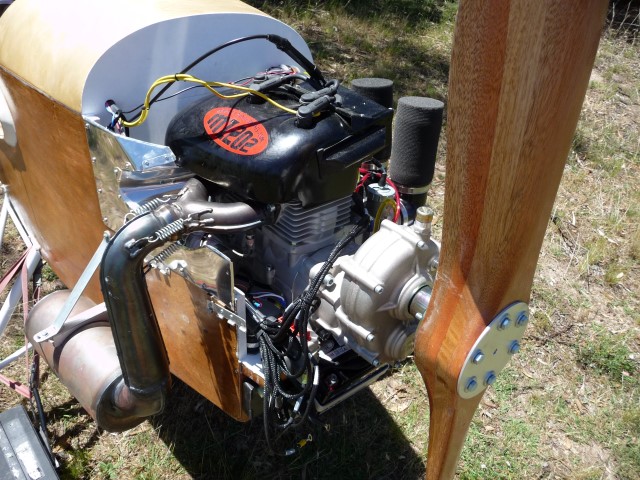
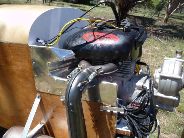
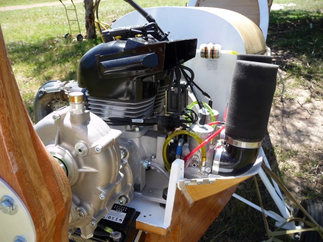
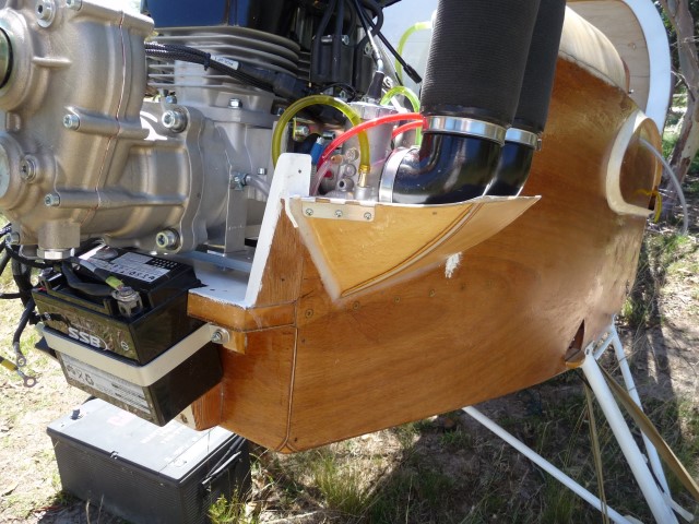
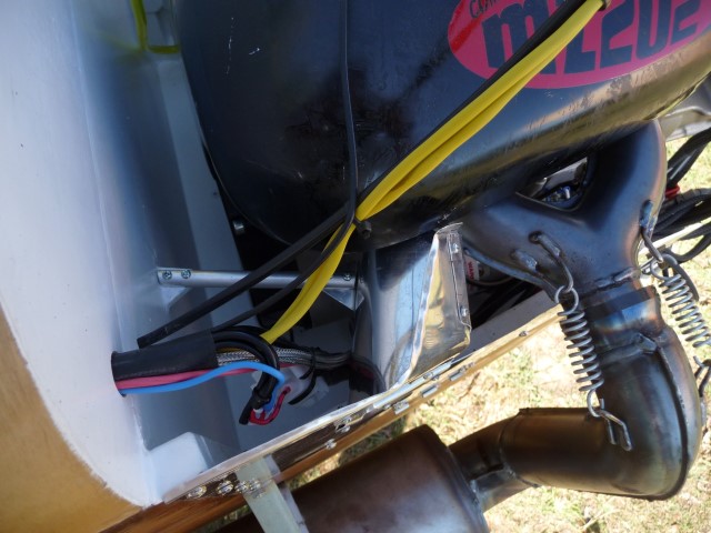
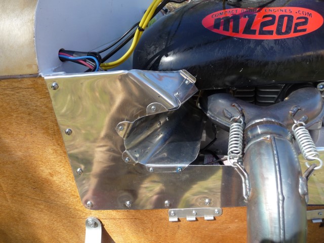
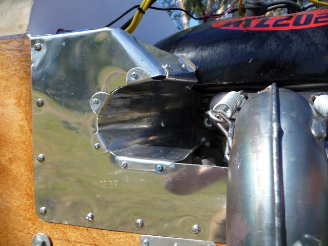
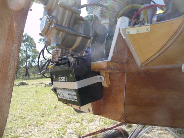
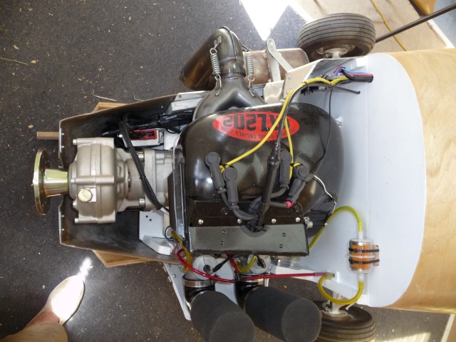
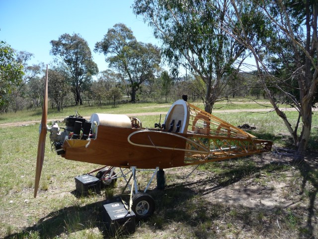
I've posted elsewhere about my engine, but it rightly belongs in this thread. So please forgive any repetition. I bought the Eros kit intending to use a Rotax 503, but then found the old model I had was not worth rebuilding. After much research & thinking about which way to go, I bought a new MZ 202 from Compact Radial Engines in Canada. Leon Massa (main man) is very helpful, and makes a superb engine. I weighed it next to the 503 and it is 22lbs lighter - and that includes electric start. and it is 60h.p. conservatively. It doesn't drop straight in to the engine bay. The fan is direct drive, & quite a large diameter, so this forms a step that extends below the level of the mounting feet/engine bay floor. This meant I had to make a cutout in the floor, and a cover which screws in place to seal off the engine bay from the cockpit. The other major difference is that the 202 uses reed valves, unlike the piston porting on the 503. The reed valve arrangement requires the carburettors to be at crankshaft level, or some 4" lower than the Eros cowl is designed for. I still wanted to enclose the carbs, so I made an extension to the port lower bulge on the standard cowl. I found some thick plastic pressure elbows in the plumbing department of my local hardware store, & with a bit of fettling these provide a means of getting the air filters in an upright position within the standard cowl. The lower minicowl addendum won't be too noticeable when the final paint is done - I hope. Other than that, the engine fits well in its designed space. Because it is so much lighter than a Rotax 503, I bought a fairly large battery, and mounted it as far forward as I could. It needed to be at an angle to fit in forward of the nose bowl, so I bought a sealed battery that can be used in any position (even upside down, though I hope never to find out whether it still works in that configuration). I was a bit concerned about the airflow from the exhaust manifold being sucked into the cooling fan inlet, so I modified the standard aluminium baffle by adding a scoop. This almost abuts the exhaust face of the cylinder, & is swept back to encourage the backwash of hot air from the manifold Y piece to exit from the stbd cowl bulge rather than the fan. I have made additional cutouts in the cowl to allow the airflow coming in to exit, because although there are 5 cutouts facing forwards to allow air in, there is very little provision for the air to get out. But I will post some pics of the cowl later. And with at least 60 hp under the cowl I want to let all that heat out. Early last week I rolled out the fuse & fired up the engine. I was very pleased with how well & smoothly it ran. Youtube link here: https://www.youtube.com/watch?v=MJ1AppoTblw&feature=youtu.be
|
|
 |
|
|
|
|
|
|
| beragoobruce |
| November 29, 2015, 1:55am |
|
Built an Eros - now I'm flying it! AcePosts: 1,067
Time Online: 19 days 10 hours 58 minutes
|
|
|
|
|
|
| beragoobruce |
| November 29, 2015, 1:56am |
|
Built an Eros - now I'm flying it! AcePosts: 1,067
Time Online: 19 days 10 hours 58 minutes
|
|
|
|
|
|
| aeronut |
| November 29, 2015, 12:12pm |
|
blue sky and tail winds to everyone AcePosts: 1,560
Time Online: 28 days 22 hours 31 minutes
|
In the video of the engine run it appears that there is a clutch between the prop and gear box, is it a feature of the gear box? |
| never surrender; never give-up |
|
|
|
|
|
| beragoobruce |
| November 29, 2015, 12:32pm |
|
Built an Eros - now I'm flying it! AcePosts: 1,067
Time Online: 19 days 10 hours 58 minutes
|
Yes, it's a centrifugal clutch before the gearbox. It stops gearbox chatter at tickover - works very well.
Bruce |
|
|
|
|
|
| beragoobruce |
| November 29, 2015, 12:33pm |
|
Built an Eros - now I'm flying it! AcePosts: 1,067
Time Online: 19 days 10 hours 58 minutes
|
And it also means you can practice proper deadstick landings. Fun! |
|
|
|
|
|
| aeronut |
| November 29, 2015, 4:29pm |
|
blue sky and tail winds to everyone AcePosts: 1,560
Time Online: 28 days 22 hours 31 minutes
|
Yes I think that is a good feature. I start my 447 and idle it at about 2000 rpm but throttle all the way down as I get in and I think that must be hard on the gear box so I idle it right back up after getting seated. |
| never surrender; never give-up |
|
|
|
|
|
| PUFF |
| November 30, 2015, 4:20pm |
|
 Ace AcePosts: 1,518
Time Online: 34 days 6 hours 18 minutes
|
Be very careful with that LUGGAGE compartment.
You can easily get your Weight and Balance out of kilter and make a huge mess.. |
|
|
|
|
|
| beragoobruce |
| November 30, 2015, 7:29pm |
|
Built an Eros - now I'm flying it! AcePosts: 1,067
Time Online: 19 days 10 hours 58 minutes
|
Thanks for your concern, Puff. I realise it's a temptation to overload, that was why I said in my original posting that I will need to establish a safe weight when I do my weight & balance trials. And to placard the max weight that keeps me within allowed c.g.
But without a baggage bay, where do you carry things like a tent & sleeping bag? Light but bulky items.
Bruce |
|
|
|
|
|
| stevejahr |
| November 30, 2015, 9:47pm |
|
 Airbike plans examiner AcePosts: 200
Time Online: 4 days 11 hours 43 minutes
|
The other way to insure the fan does not suck up hot air... is to provide an intake duct to the fan. Although the metal duct/cowling around the exhaust makes a lot of sense. |
|
|
|
|
|
| beragoobruce |
| December 1, 2015, 10:24pm |
|
Built an Eros - now I'm flying it! AcePosts: 1,067
Time Online: 19 days 10 hours 58 minutes
|
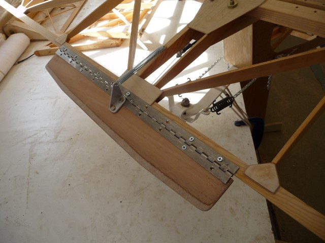
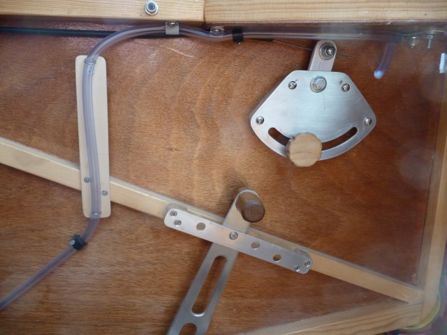
Here's some photos of my elevator trim & control in the cockpit. On the trim control, the knob at the bottom of the quadrant is both handle & locking device. You unscrew 1/4 turn, move along the quadrant, & tighten up. I will add some markers for takeoff & landing settings after I fly.
Also a photo of my throttle control. This time the locking knob is in the centre. But the carburettor springs were too strong, so I added a bungee on the lever to reduce the force needed for the lock to hold better under vibration.
Bruce
|
|
|
|
|
|
| PUFF |
| December 3, 2015, 12:20pm |
|
Ace
Posts: 1,518
Time Online: 34 days 6 hours 18 minutes
|
Shoudn't the spring on the trim tab be on the bottom? |
|
|
|
|
|
| texasbuzzard |
|
 airbike Buzzard AcePosts: 1,238
Time Online: 8 days 23 hours 51 minutes
|
I believe the setup Bruce has is correct as the trim tab will always be in the down position. the force will be on the cable not the spring.
monte |
|
|
|
|
|
| beragoobruce |
|
Built an Eros - now I'm flying it! AcePosts: 1,067
Time Online: 19 days 10 hours 58 minutes
|
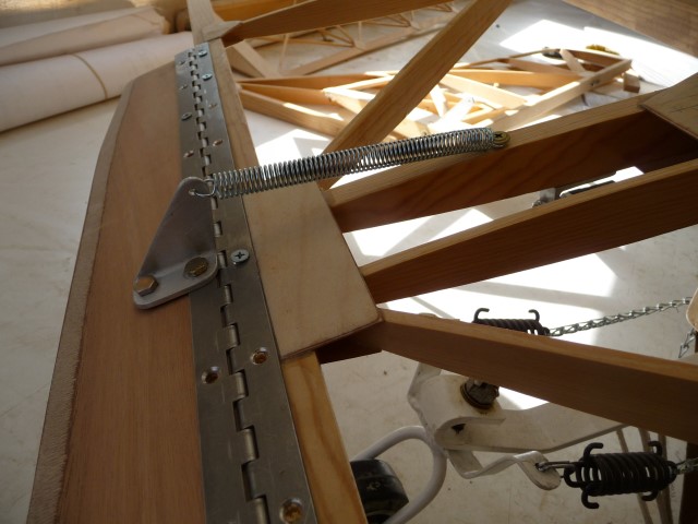
I'm not sure it makes a lot of difference as regards function. I put the spring on the top for two reasons.
Firstly, if the cable breaks, or the friction device loosens, the tab will make the elevator go down, which means the plane will go into a dive while my ancient brain figures out what went wrong. I'd rather this than a sudden nose up.
Secondly, I was able to exit the cable via the elevator pushrod tube, which means there is less bending on the cable outer as the elevator moves up & down. It also makes it all a bit neater.
Of course I may be missing something, so criticism welcome.
Bruce |
|
|
|
|
|
| beragoobruce |
|
Built an Eros - now I'm flying it! AcePosts: 1,067
Time Online: 19 days 10 hours 58 minutes
|
Quoted Text
The other way to insure the fan does not suck up hot air... is to provide an intake duct to the fan. Although the metal duct/cowling around the exhaust makes a lot of sense.
True, but there is an inlet duct of sorts in the Eros cowling. It is an inlet towards the aft end of the cowl, & positioned such that the outside air feeds the fan. My metal shroud was just to inhibit hot air reaching the fan. |
|
|
|
|
|
| aeronut |
|
blue sky and tail winds to everyone AcePosts: 1,560
Time Online: 28 days 22 hours 31 minutes
|
I noticed that the exhaust manifold springs are bare. You will probably pass a piece of safety wire through the center of the spring connecting the two parts of the exhaust manifold together and I applied a line of hi temperature silicone along the length of the spring, I am told it helps with the vibration of the spring and the wire helps to hold the spring parts on to the engine should the spring break. I have had one spring break on my Max. I do realize that you were only running up the engine to see if sounds like a Merlin (lol) but I would do this before the first flight.  |
| never surrender; never give-up |
|
|
|
|
|
|


 Logged