Print Topic - Archive
ETLB Squawk Forums / miniMax, Hi-Max, and AirBike General Discussions / Eros build in Oz
Posted by: beragoobruce, August 31, 2014, 12:19am
So it’s Sunday & I’m taking a day off from my build to do some other stuff. I think my wife thought I’d left the country a month ago :) One of our sheep has just had twins, the fire season is starting soon & I have some training to do, and my little Suzuki DRZ needs a workout (don’t forget here in Australia tomorrow is the first day of Spring). And I keep meaning to post on my build.
In the posts which follow, I’d like to make it very clear that none of what I say is intended to be any sort of “how to” advice (as if!!). The way I’m building is what works for me: it’s not the only way or even the right way – it’s just a record of what I’m doing (complete with mistakes).
In my early days of looking around for which plane to build I found this board incredibly helpful. I spent many long & enjoyable hours going through every single page of the current forum, and some of the old one. Loved it! So much useful info from so many people. So this is my contribution for the interest of others. For what it's worth.
I downloaded the plans and looked through them all for days until I got a feel for how it all went together. They are a bit daunting at first, but everything is there if you look long & hard enough.
So I decided the MiniMax was for me. I went for the shoulder wing, just because I prefer its looks to the high wing. Originally I was going to go as light as possible, with the smallest engine. But then I thought it through and decided that I’d prefer a bit of margin on power, and that with a bit more effort I could build a more ‘finished’ looking plane. So eventually I went for the Eros, & having started with the 1100R I finished at the other end of the scale. I think all the Max family look great, but I felt that with all the time, effort & money it was going to cost me I’d build the one I most liked.
I was going to scratch build. But it’s very much harder to do that in this country, as there are so few people homebuilding. Almost everything would have to come from the US, with attendant shipping costs. Although we have hoop pine here, which is pretty much the equal of spruce, I would have to order it blind and pay the huge shipping costs we learn to live with in a small market with little competition. So in the end I decided to pay the extra and buy the complete kit. If I lived in the UK or the States, I think I’d scratch build.
Anyway, I’m posting my build story so others can take from it what they will. But bear in mind that as builders we all make our own decisions, and as manufacturer, you are responsible for your own product. I've no doubt that some here will not approve of some of my decisions, or the way I do some stuff, and that’s fine. I hope they’ll post & we can discuss the alternatives.
My posts will be irregular, but I hope to go all the way through to first flight (if I live that long).
Cheers
Bruce
Posted by: beragoobruce, August 31, 2014, 1:08am; Reply: 1
Having read how tedious it is making ribs, I decided to make those the first part of my path down the looong road to building my plane.
I didn’t like the idea of stapling into thin bits of spruce, fearing that it would split. But I did like the Rib-O-Matic posted here
http://www.lonesomebuzzards.com/cgi-bin/forum/Blah.pl?m-1389382017/s-19/highlight-rib+o+matic/#num19 by Peter. So I made my own version while waiting for my kit to be delivered.
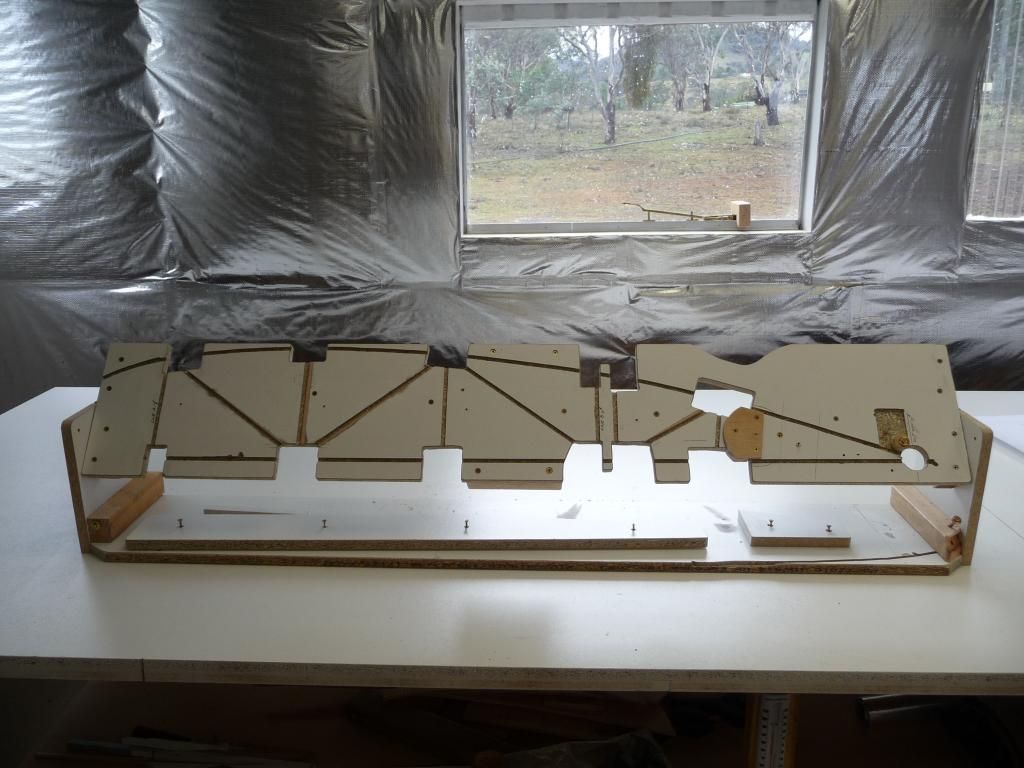
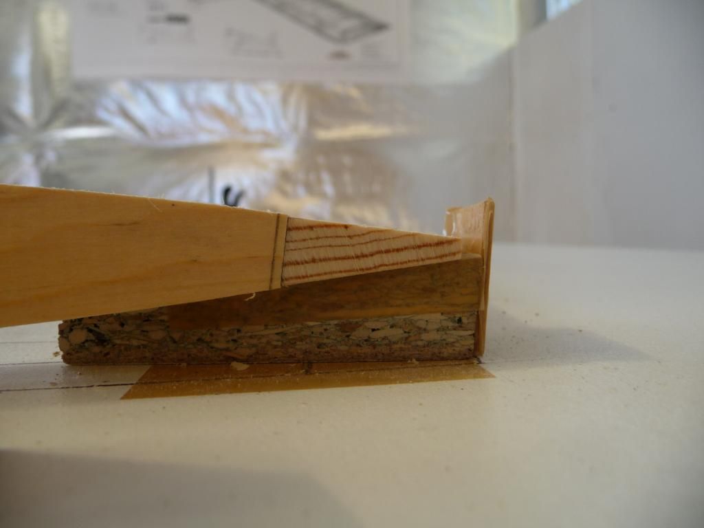
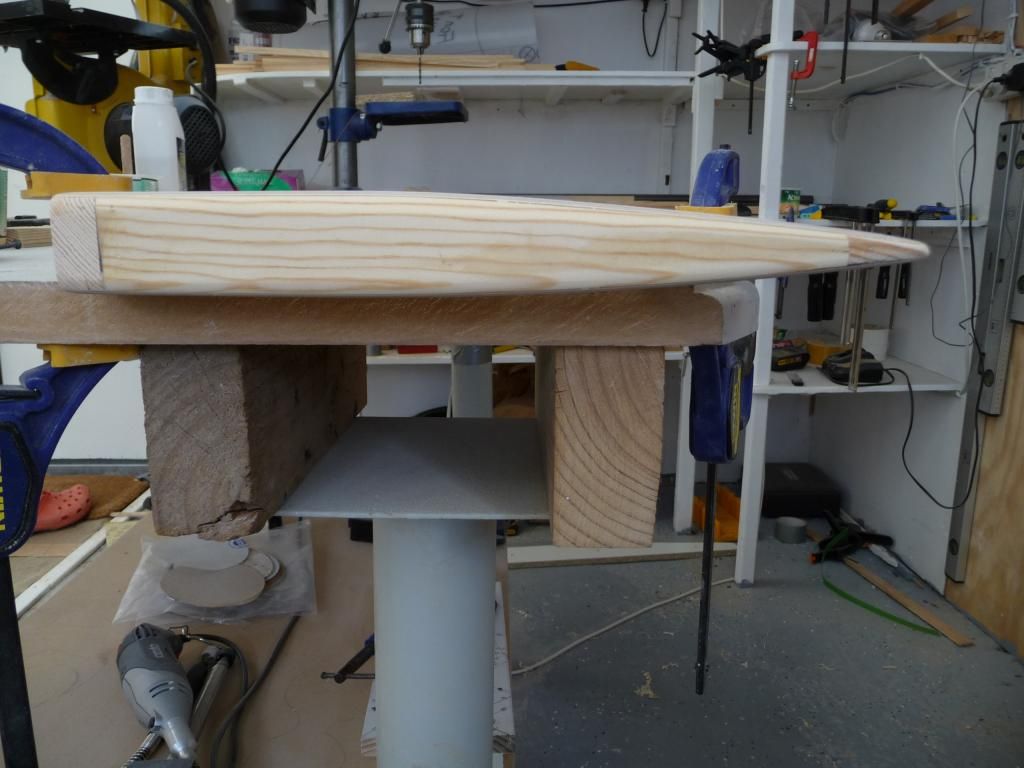
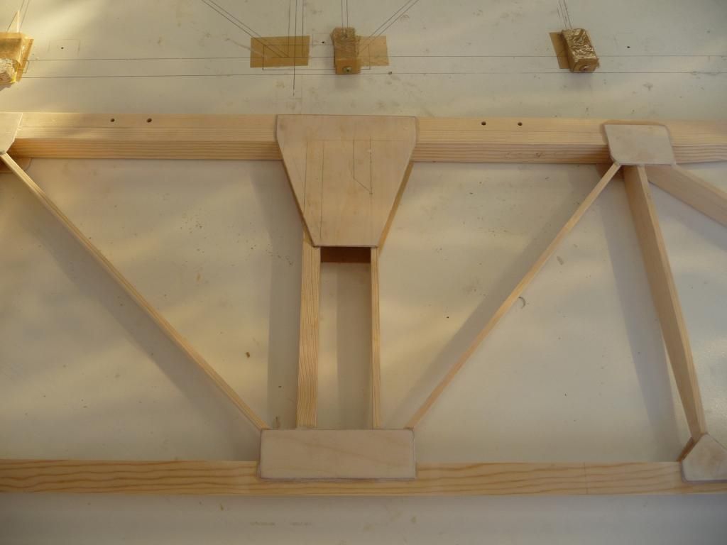
When the great day arrived, and I’d unpacked, checked, & stored all my bits of wood, aluminium, fasteners, and all the rest that go to make up this ‘simple’ aeroplane, I got to work on the RS1 rib members. I cut them all carefully to size, and assembled them in my jig. I cut the first batch of gussets, and dry assembled them onto the jig.
Disaster. . . I found I just couldn’t get the jig to do its job. When I tried to clamp the gussets each side of a joint, using a large spring clamp, the weight of the clamp meant that the gussets didn’t stay flat on the surface of the RS1. I fiddled around, but just could not get an even mating of gusset to rib member – and it was hassle to keep flipping the jig over to align both gussets.
Now I’m sure Peter’s Rib O Matic works very well, but after spending half a day trying unsuccessfully to get my poor imitation to work, I gave up and made a jig exactly according to the plans. It works very well. An omen?
I dry assembled everything into the jig to check, then glued and stapled. I carefully eased out the assembly, and glued & stapled on the remaining gussets. Easy, if a bit fiddly & time consuming. And no matter how close to the edge of ply or spruce I put the staples, neither ever showed any tendency to split.
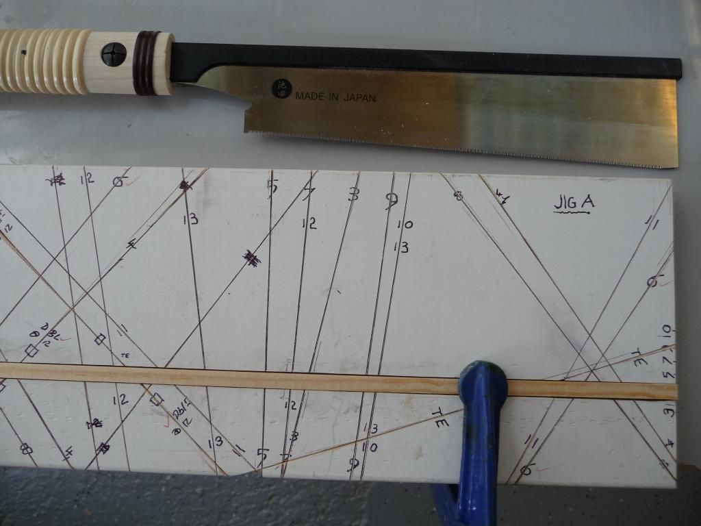
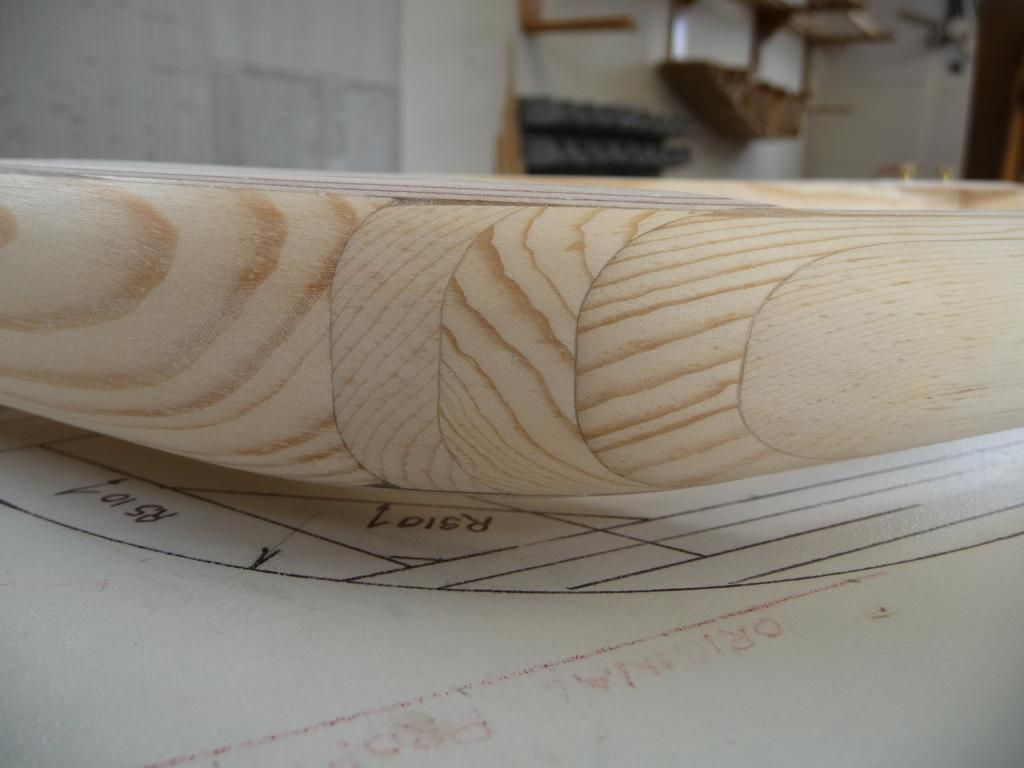
So I made a rib member cutting jig to ensure all my ribs would be identical. They might be wrong, but at least they’d all be uniformly wrong. It's worth noting here that the airfoil section as printed on the plans takes a bit of artistic licence to reproduce.
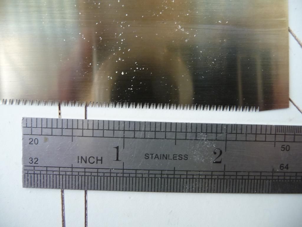
I used a Japanese pull saw to cut the RS1 & the jig saw guides. I’d never seen these before, but someone on this board recommended them, & I took a chance. They’re absolutely brilliant for very fine cuts on small cross section wood, and cut the RS1 beautifully. The blade is more like a knife, with about a million teeth per inch, and the slot it makes split the lines I’d marked on the cutting jig with an ultrafine ball pen. The blade is 0.2mm thick and the kerf (cut width) is 0.28mm wide (that’s 0.008” & 0.011”)! Clever chaps, these Japanese.
I soon found that each rib member has to be fitted individually, owing to the variation in RS1 dimensions. Since I wanted the outside profile to be constant, any variation in the width of the top & bottom members means the internal lengths will vary. This could be avoided to a great extent if the inside members were just cut with square ends, letting the gusset take all the shear loads, but I’d rather take a bit longer & fit the parts together accurately. Just gives a bit of redundancy & guards against a poor glue job.
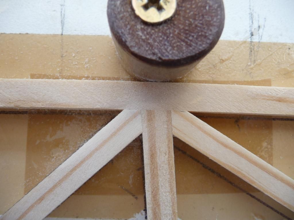
Note that I use thin brown parcel tape as a release agent under the joints, to stop the epoxy sticking to the jig. It's cheap, easy, and semi transparent.
So I built each rib individually, cutting the RS1 in my jig & dressing the ends on my little 5” disc sander. This is quite quick once you’ve done a few hundred ribs. . . I found 120 grit to be good for this, as it leaves a slightly rough surface which should improve glue bonding. I use a small flat (needle) file to 'de-whisker' the wood afterwards.
Next post on mixing T88 and cutting gussets.
Posted by: lake_harley, August 31, 2014, 1:27am; Reply: 2
Great to hear you've started construction. I have the feeling your posts are going to be interesting and probably very helpful for others just getting started too.
I do have one question though....that white board with all the lines.....is that actually a "jig" for cutting your rib parts? If it is I'm sure you understand what you have going there, but I'm baffled.....not that being baffled and confused is new to me or anything :-/
I like the way you fitted the joints on the rib. I didn't fit mine nearly that perfectly, but I couldn't stand the idea of just cutting them square either.
Keep us updated.
Lynn
Posted by: beragoobruce, August 31, 2014, 5:08am; Reply: 3
Hi Lynn
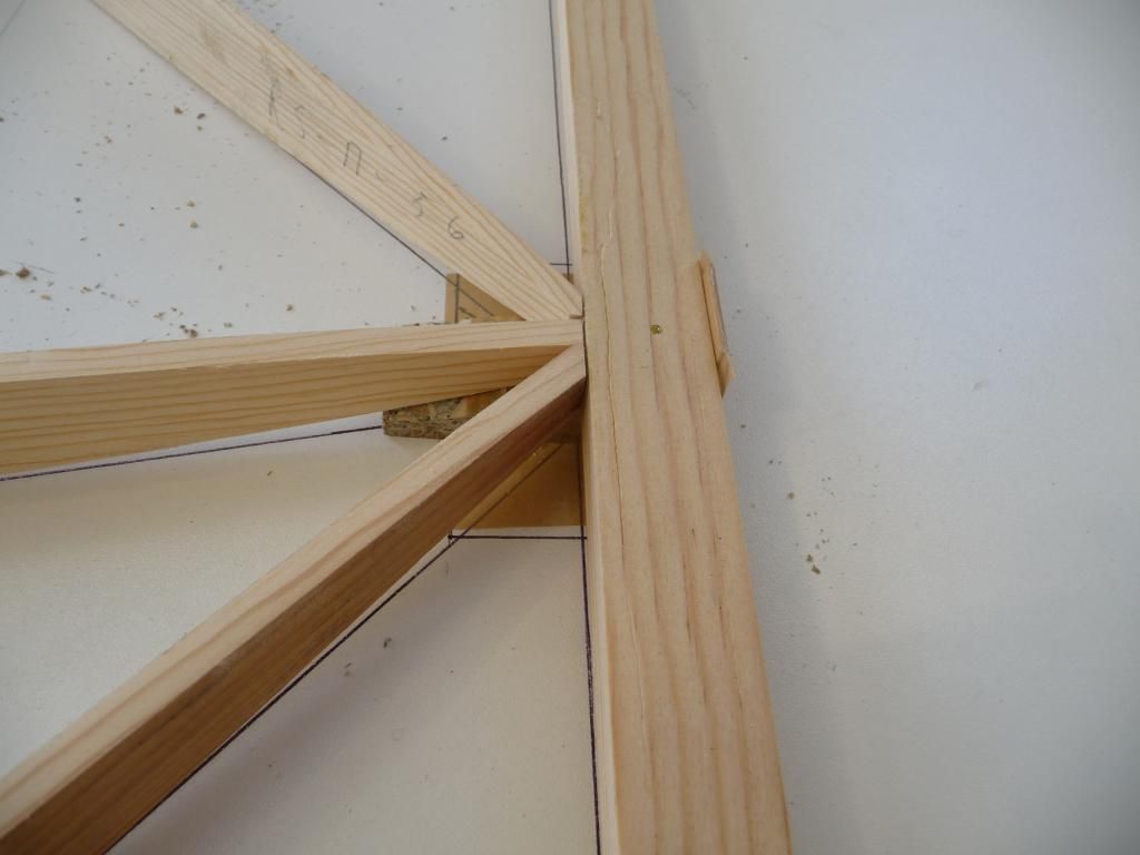
Yes, that's a cutting jig. I routed a channel just under 1/4" deep along the length - that's a piece of RS1 located in the groove in the photo.
The lines are actually grooves cut 1/4" deep across the full width of the jig. If you look carefully at the third photo you can see the groove is thinner than the black line. The pull saw locates in these guide grooves so that the RS1 stock is cut at the correct length & angle for its place in the rib.
I numbered all the elements of the rib (1 is top member, 2 the bottom, then 3-13 for the uprights & diagonals) so I could cut each part the correct length.
The cutting jig took a little time to make, but it saved measuring & marking each little bit of rib over & over again.
Posted by: Bones, August 31, 2014, 1:32pm; Reply: 4
beragoobruce,
Hello! Well, I can see already that I'm going to follow, and enjoy, the updates on your "build." There's an abundance of experience and help on this Board if you need it. Glad you're here, good luck....And get busy!!
Bones
Posted by: lake_harley, August 31, 2014, 2:52pm; Reply: 5
Thanks for the explaination of the jig. That made the photo make more sense. I'd bet that did take some time to develop! Considering the hours I recall spending, cutting and then fitting rib parts, I can imagine it would save time overall.
Lynn
Posted by: Tom, August 31, 2014, 5:23pm; Reply: 6
It is probable that the rotating Rib-O-Matic type jig gave deflection problems simply because the clamps were too heavy. I've done a lot of finicky gluing over the years and I think the "clamps" for this type of jig would probably best be spring wooden clothes pins. The ones I use open about 12 mm which is enough to hold both gussets in place. For gluing thin plywood to thicker member you can cut one side of the jaw off and glue the pin to a block of wood with a "jaw" cut on the lower edge. These are very light. Small plastic hobbiest clamps also work great. A huge number of folks on this site probably know this, but I thought I'd mention it.
Tom
Posted by: beragoobruce, September 1, 2014, 3:56am; Reply: 7
Thanks, Tom. I like the idea of the modified wooden peg. The clamps I used on my first jig were the same as the ones in Peter's pic of his jig, they're black plastic with orange softjaws. I don't really like these very much, and a couple have broken on me - just snapped.
I have various designs of clothespegs to try out, and I may go for the plastic pipe clamp idea if I run out. I'd actually prefer lots of various sizes of G or C clamps, but of course they are much more expensive than spring clamps.
Posted by: Tom, September 1, 2014, 12:00pm; Reply: 8
The plastic pipe clamps may be a better idea than the clothes pins. I have no experience with them, but they sound like a good solution.
Tom
Posted by: beragoobruce, September 13, 2014, 2:54am; Reply: 9
I've found it only takes about 15g grams of T66 to glue a whole rib. I wanted to be accurate in mixing parts A & B, so decided to do my mixing by weight rather than volume. So I bought a small digital scale from ebay, similar to this:
http://www.ebay.com.au/itm/0-1g-500g-DIGITAL-POCKET-MINI-WEIGHING-SCALES-JEWELRY-GOLD-SILVER-WEIGHING-/181367379869?pt=AU_B_I_Electrical_Test_Equipment&hash=item2a3a56979d&_uhb=1I use small yoghurt pots for mixing, and wooden coffee stirring sticks for spreading. I taper them a bit first on my disc sander.
For a rib, I weigh out 8g of part A. It usually goes over a bit, say 8.2g. Then I note whatever amount went in the pot, and multiply it by 0.83, since of course the ratio of A to B is 100:83. I do the calcs with my calculator & jot down the numbers before I add the part B, so I don't forget & have to dump that batch.
So for a mixing pot weighing 4.4g, and 8.2g part A, my calcs would look like this: 4.4 + 8.2 =12.6 For part B, 8.2 x 0.83 = 6.8
Total weight = 19.4g
It sounds more complicated than it is in practice, and this method means I can be sure the epoxy is properly proportioned. I don't want to worry about the glue when I'm flying!
Cutting gussets got pretty tedious. I made a master for each position on the rib, then traced round it to make 4 or 5 on a strip of gusset ply. Then cut 4 lengths the same, and stacked these together. I cut out following the top pattern using my bandsaw, and finish on the disc sander. Then I put 2 together, and bevel the edges each side on the sander, so I know I have one of each hand. Then I put them in a plastic coffee cup marked with the correct position. This way I finish up with lots of plastic containers with lots of gussets, all sorted so I don't have to stop to make some more just after mixing up a batch of epoxy.
For the area behind the rear spar that will be cut away to form the aileron, I wanted to make sure no glue found it's way to cause problems later. So I taped the no glue area on the upper & lower RS1 members with brown parcel tape, which is quite good as release tape.
It was great to finish the last plain rib and start the tip & root ribs.
And I found a new use for the sanding former Dave sent me - you can drink coffee out of it when you're done sanding :)
For the aileron central support at rib #5, I didn't feel comfortable with just half a hole providing the central bearing.
So I added a block of 3mm ply to the area of the hole, & glued it in place.
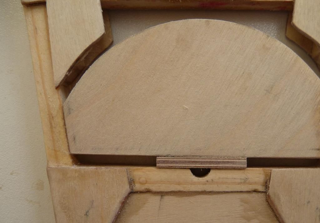
Then made a template/drill guide out of 1/4" ply, and re-drilled the 1/4" dia pivot hole.
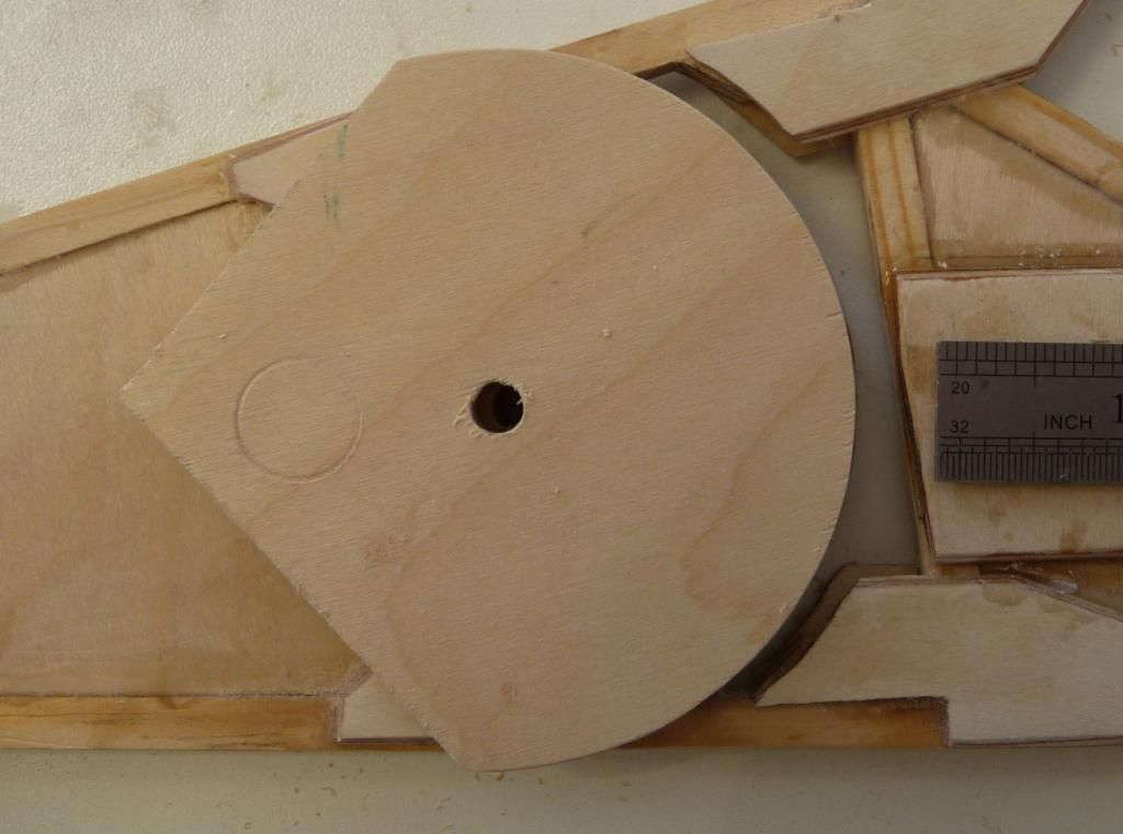
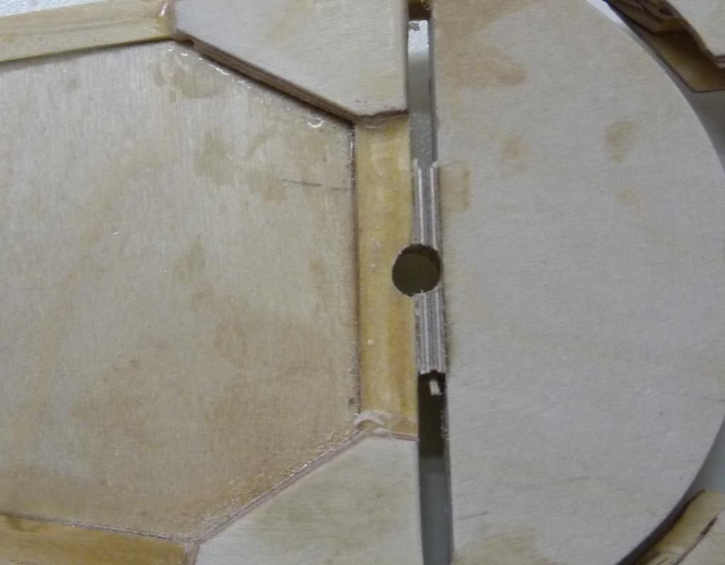
I feel there's a bit more support now around that bearing.
It's great to have finished all the ribs, and to start on the next bit. Incidentally, the lumpy bit on the end of the root & tip ribs is protection for the very delicate sharp end of the trailing edge. I taped a coffee stirrer stick to the rib to guard the corner.
24 ribs done, empennage next. Yaay!
Posted by: lake_harley, September 13, 2014, 3:43am; Reply: 10
Nice!!! I look forward to the next post. Cool lighting effect in the photo of the ribs....artsy.
Lynn
Posted by: beragoobruce, September 13, 2014, 3:54am; Reply: 11
Entirely accidental - but thanks anyway! On looking at my other pics, the photos are really brutal. They seem to pick out all the glue smears and less-than-perfect details. I thought my ribs looked alright until I saw them on this post. Oh well, I'm pretty sure they're good structurally.
Posted by: Arthur Withy, September 13, 2014, 10:14am; Reply: 12
Hi Bruce.
..I believe in the KISS principle....so you lost ME with all that MATHS...I have to ask myself ...WHY...?
Just head down to the local chemist....buy 4 of the 50ML syringes....about a $1 each....and then mix by volume......so easy and it works....and focus on the build not the ....other stuff.....just my opinion I do know you have lots of experience....I just love the KISS principles
Also love your pics...great work, and well done. :)
cheers Arthur
Posted by: beragoobruce, September 13, 2014, 12:26pm; Reply: 13
Yes, I know it looks like hassle, but it's very easy if you have a calculator on the bench.
I've tried using syringes with epoxy in the past, & it doesn't work for me. The poxy is so gloopy it gets everywhere. And if you use scales, you can accurately mix any quantity, down to a couple of grams, even.
And it was great to finish both bottles of epoxy at exactly the same time, so I know it works.
Whatever flies your plane!
Posted by: Arthur Withy, September 13, 2014, 12:33pm; Reply: 14
whatever flies your plane...hmmmm ...well its not airspeed....its like all women...Usually Money.....
Posted by: beragoobruce, September 28, 2014, 7:40am; Reply: 15
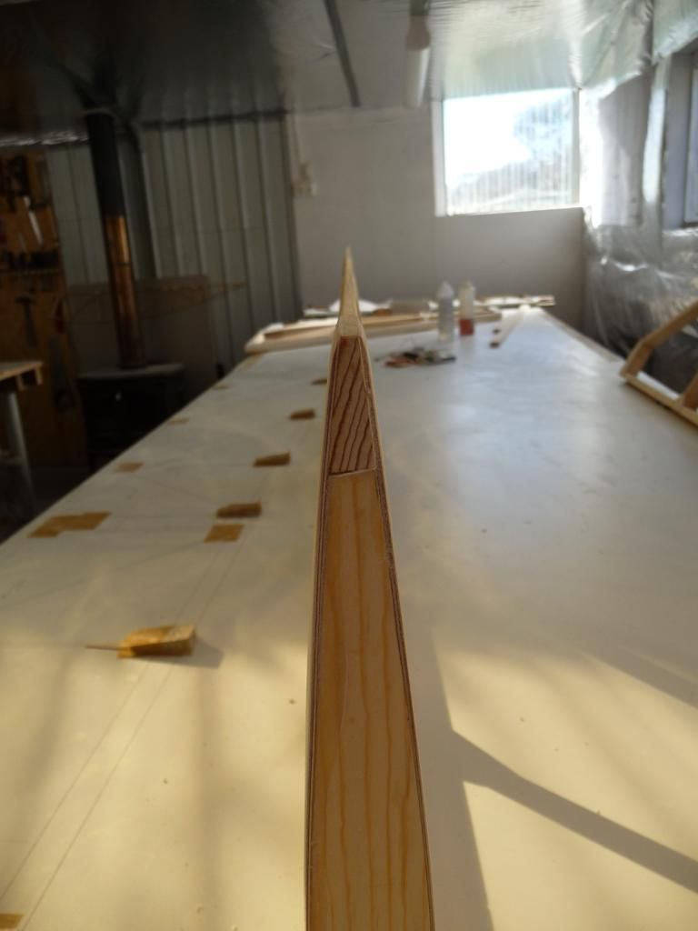
After all those ribs it was great to start on something different, so I made the fin, rudder and tailplane next.
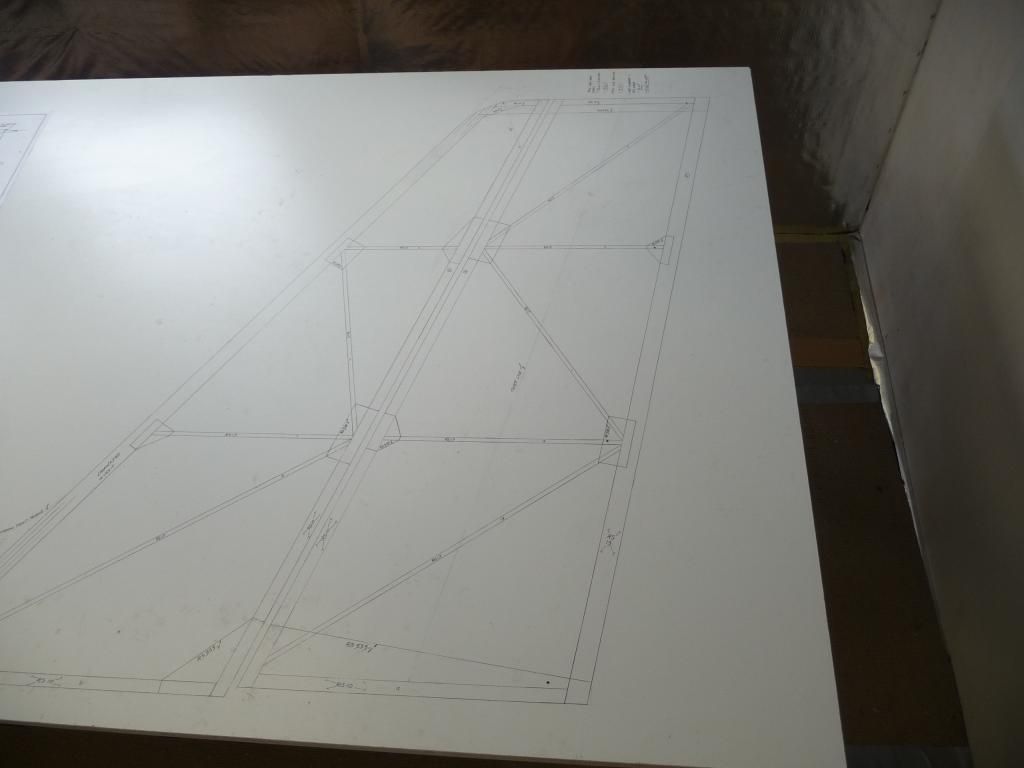
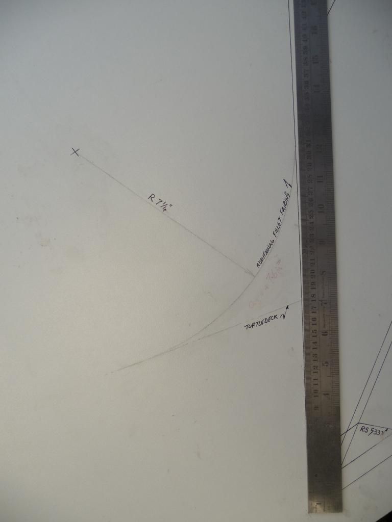
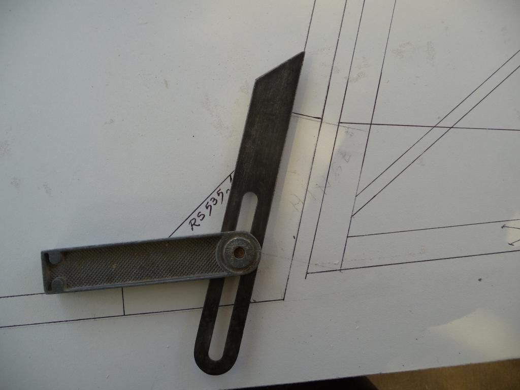
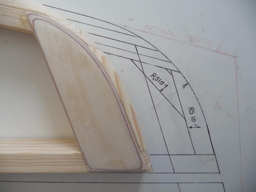
I drew the plan on my white melamine worktable with a fine tip marker pen. I prefer the softer lines of some large radius corners to the fin & tailplane. I also plan to fit a dorsal fillet where the fin joins the turtledeck. And I made the top edge of the fin & rudder parallel to the base of the fin. This is just aesthetics, but it’s interesting to see that the proposed new 2 seater has a radiussed top to the fin.
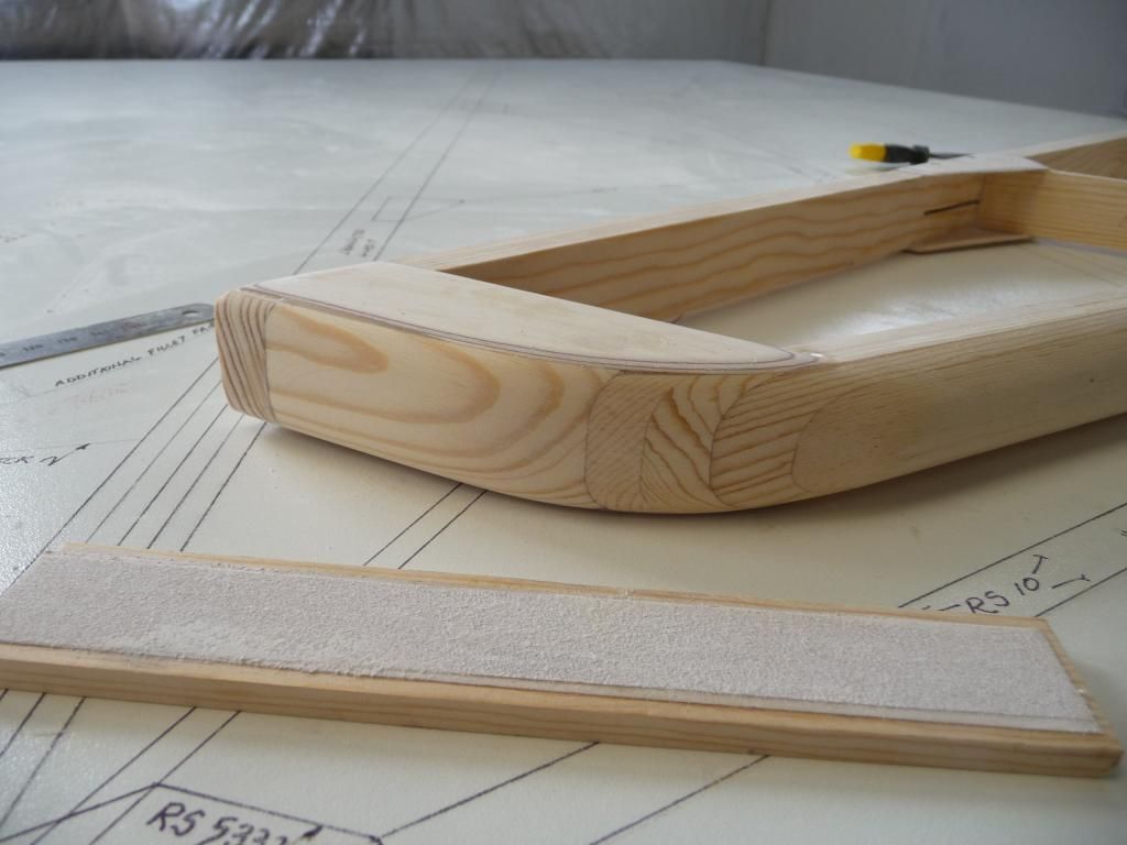
I laminated the fin leading edge, and planed it to a semi-circular shape.
I copied the angles off the plan, and marked the relevant members. Then cut them with a fine tooth tenon saw, and finished on the disc sander. I found I can get close fits this way.
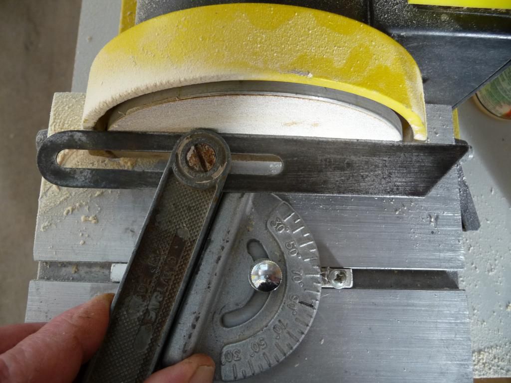
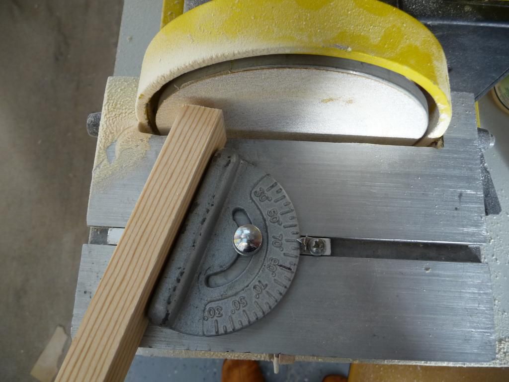
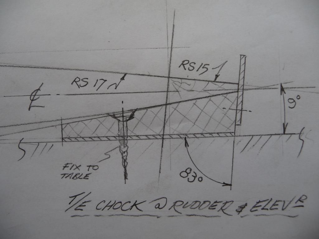
I needed some way of supporting the trailing edge of the rudder, and later the elevator, while I glued the ribs. So I measured the angle of the trailing edge section, and made up a number of blocks cut to that angle, and at the correct height. I also fixed a locating tab to the back. I covered it all in brown ‘release tape’ so I wouldn’t have to fly with blobby bits on the back edge of my rudder. . .
I added an extra small block of RS10 to ensure adequate strength at the top of the fin where I had made it radiussed.
Then glued it all, and finished it with some hand sanding. I do like working with wood – it always looks so much more soulful than metal when it’s done.
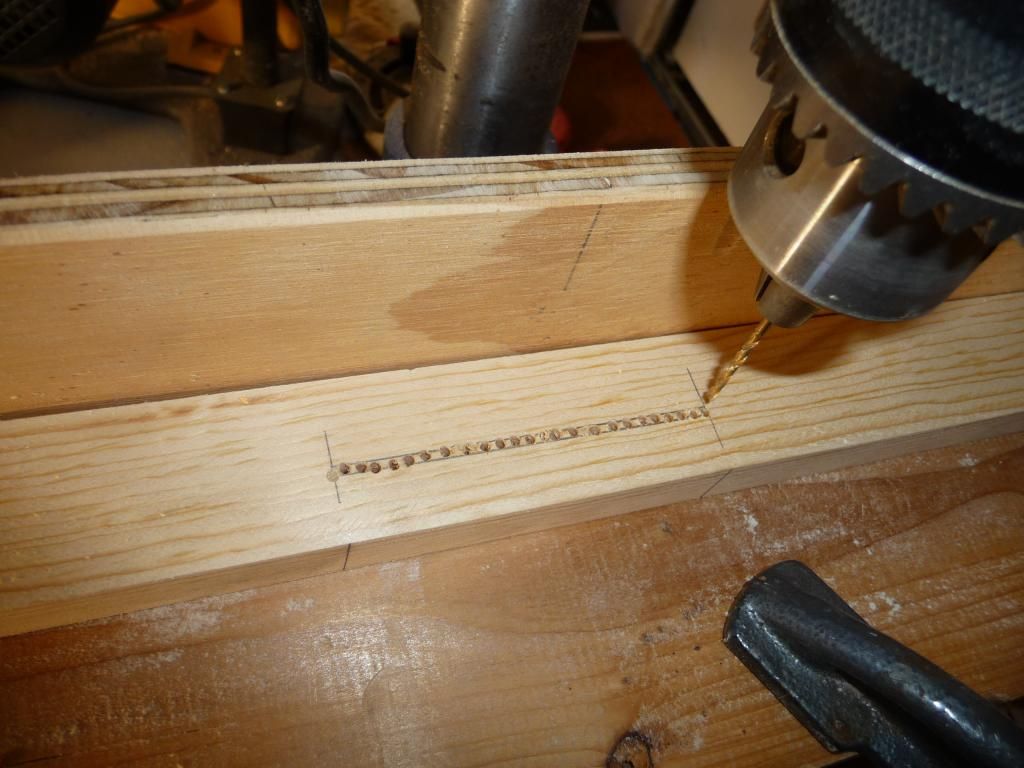
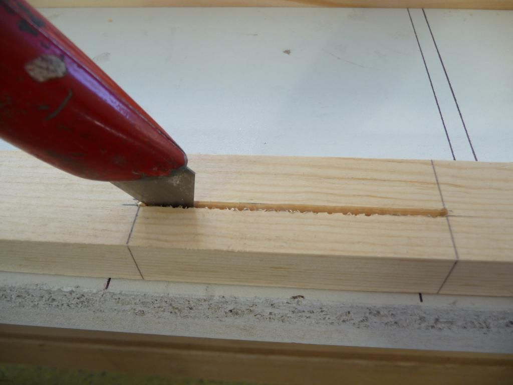
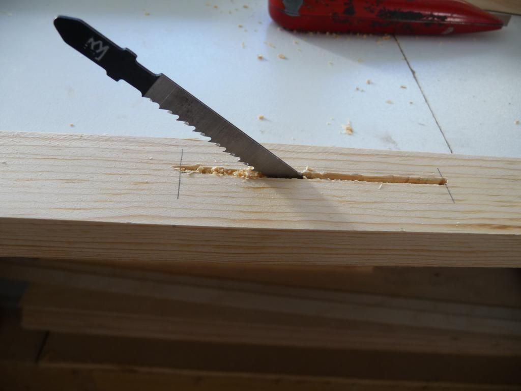
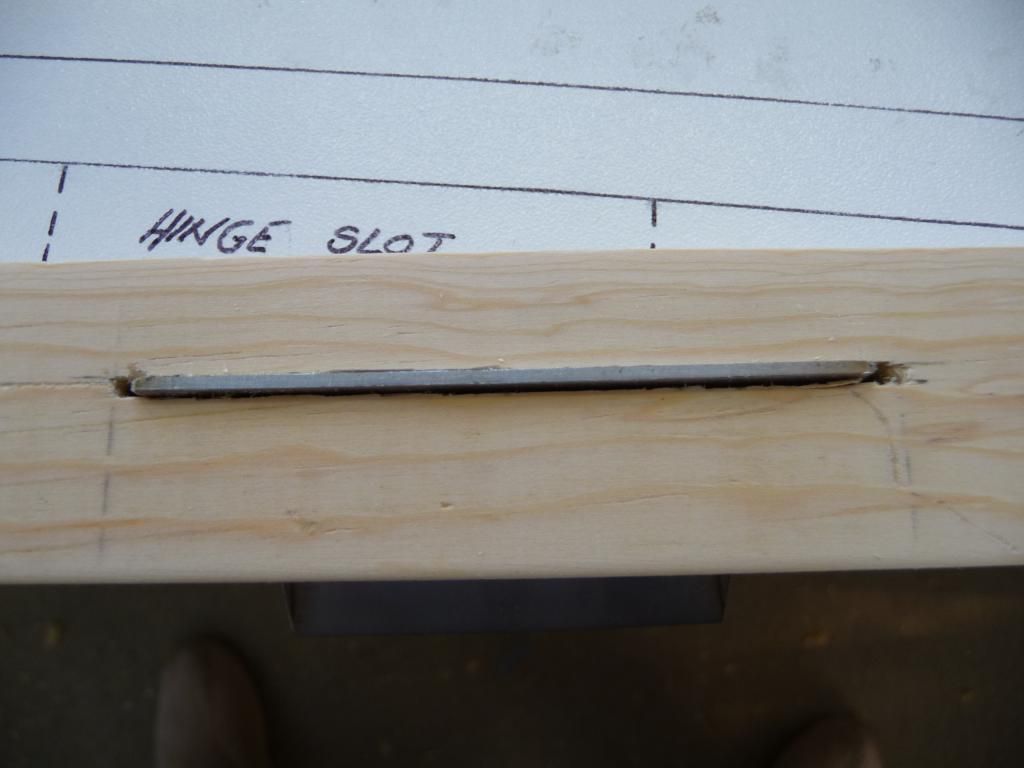
I cut the slots for the rudder (& elevator) hinges by first chain drilling, then cutting with a Stanley knife, and finally with a jigsaw blade. I used the blade by hand, as I didn’t want to risk wrecking the wood. I finished with a coarse flat needle file. The slots are quite a tight fit on the hinges.
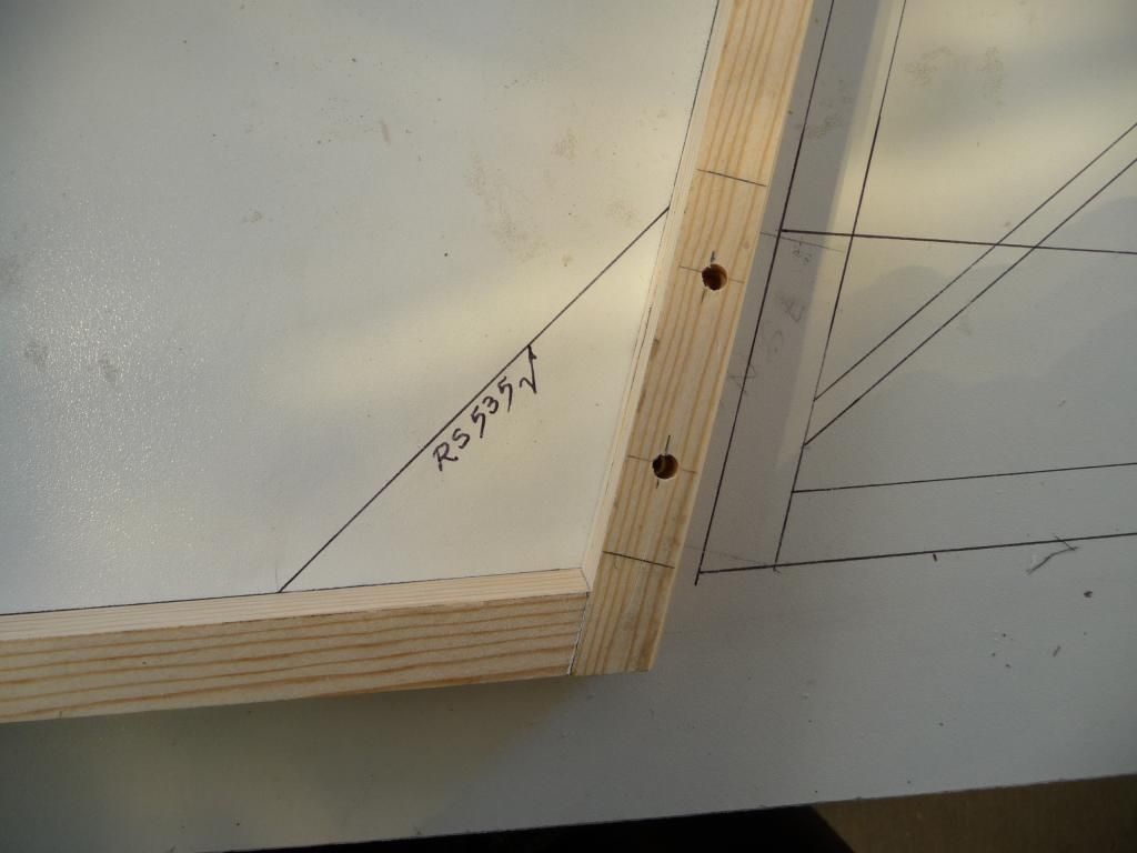
I glued on the gussets, and assembled the rudder to the fin. To achieve the required 3/8" gap between the t/e of the fin & the l/e of the rudder, I clamped the short length of 3/8" dia bushing tube between the two members before drilling the 3/16" bolt holes.
I wanted to drill the hinge holes on my drill press, rather than by hand. So I drilled the RS10 spars with the hinges in place, on the drill press, then glued the undrilled gussets on one side. When the glue had set, I backdrilled through the spars to the gussets. Then I glued the gussets on the other side, and when they were set, drilled through the whole assembly.
Posted by: beragoobruce, September 28, 2014, 8:27am; Reply: 16
I made the tailplane and elevator in the same way. Again, I wanted to radius the l/e corners of the tailplane, to match the fin.
I also added an extra rib near the centreline of the elevator, and a short length of RS10. These are because my elevator will be operated by a 1" dia pushrod, which will connect to the elevator with 2 horns, one each side of the pushrod. The extra material is to mount the additional elevator horn.
I used the t/e chocks again when gluing the elevator assembly, and was pleased with how straight the t/e was after the glue had set.
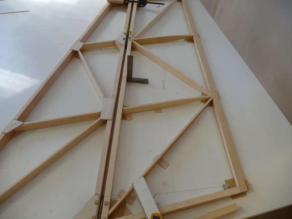
Here's the assembly before final shaping & sanding
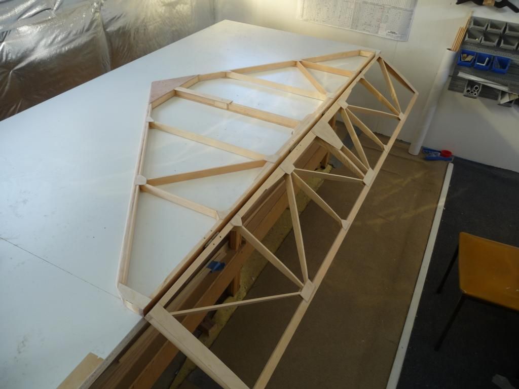
And here's the whole empannage (still with unfinished tailplane).
Fuselage next.
I suppose now I've modified the original design, both in the empennage profile, and with the pushrod control system I've drawn up, I can't call my plane an Eros any more. But I can't edit the thread title: I was trying for "Noteros build in Oz" :o
Bruce
Posted by: Arthur Withy, September 28, 2014, 9:05am; Reply: 17
Very nice work Bruce....Great photos and thanks for sharing.
and great progress too
cheers Arthur
Posted by: aeronut, September 28, 2014, 12:25pm; Reply: 18
It is always great when a plan comes together. The workmanship looks to be finist kind. If you keep on you will be flying soon. Thanks for you post, the pictures are great. :)
Posted by: bigbrixx1, September 28, 2014, 12:45pm; Reply: 19
Wow your workmanship is fantastic. I am almost embarrassed to post my build! :)
Posted by: beragoobruce, September 28, 2014, 12:58pm; Reply: 20
Thanks, guys. Don't be silly, Bigbrix - your build looks every bit as good as mine!
Bruce
Posted by: texasbuzzard, September 28, 2014, 2:52pm; Reply: 21
Bruce that is some fantastic work on your Eros. Wait till you can sit in it and make airplane sounds.
Monte
Posted by: bigbrixx1, September 29, 2014, 11:36am; Reply: 22
Thanks for the compliment Bruce. I believe my build is strong and straight! But you, my friend Are an Artist with wood. You inspire me to be better! Keep up the great work!
Posted by: Ricardo, September 30, 2014, 3:31pm; Reply: 23
Excelent work!
I like how you rounded the tail. Probably it doesn't have any effect for such draggy plane, but sure it makes a better looking design 8)
Posted by: beragoobruce, September 30, 2014, 8:59pm; Reply: 24
Thanks Ricardo. Yes, the profile change is only for looks - but looks are important too! Ask your front seat passenger ;)
Hamilton to win on Sunday?
Bruce
Posted by: Ricardo, September 30, 2014, 11:26pm; Reply: 25
Hamilton to win on Sunday?
Bruce
I rather wish another Ricciardo's win but I think Rosberg is going to recover the championship lead.
Sorry guys... just some Formula 1 chat....
Posted by: beragoobruce, October 5, 2014, 12:16am; Reply: 26
With my profile modifications maybe adding a bit of weight I decided to save a bit where I could.
The laminated leading edges of the tailplane & fin are carrying a lot of wood/weight that isn't contributing very much to strength or stiffness, so I cut the middle two laminates down to approx half width and glued them.
Saves a little bit of weight, but it all helps.
Bruce
Posted by: beragoobruce, October 25, 2014, 1:03am; Reply: 27
Having computer/satellite problems here, so different pic attachment.
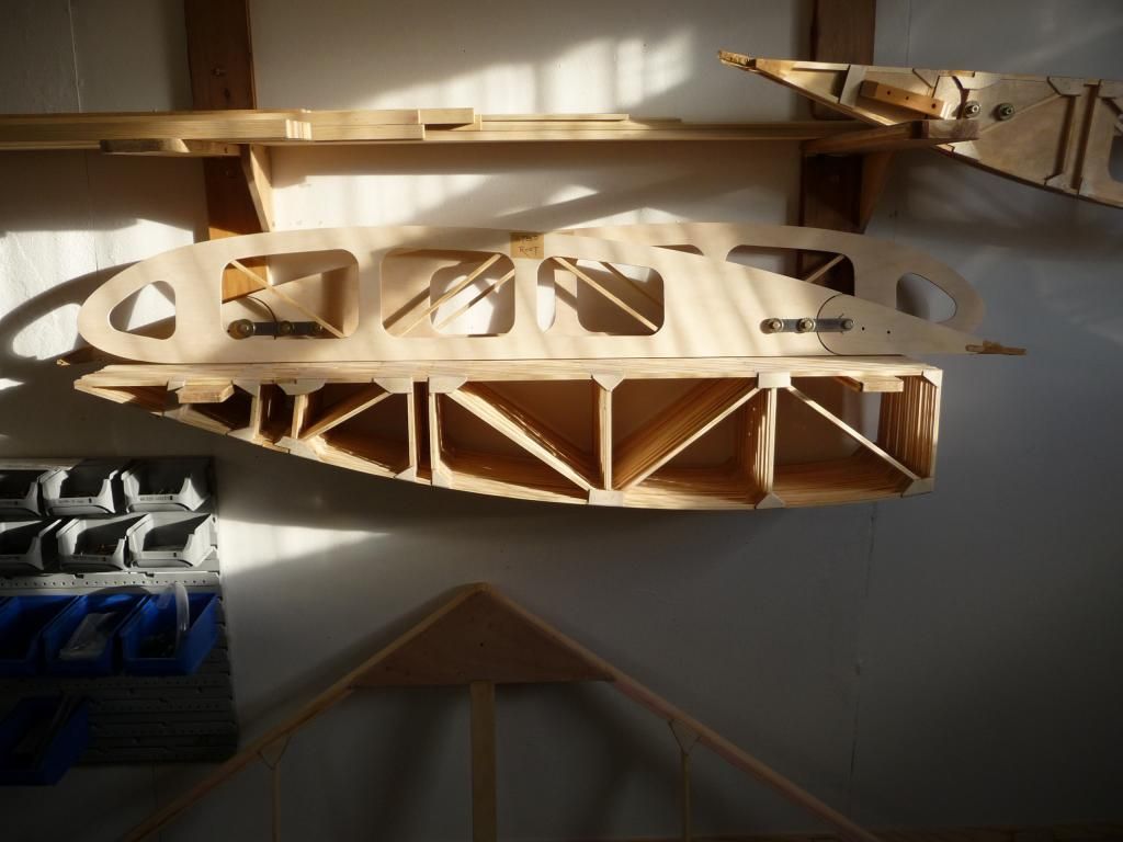
I built the two fuselage sides, the second over the first.
Posted by: beragoobruce, October 25, 2014, 1:06am; Reply: 28
I assembled the two side frames before gluing on the outside skins, to make it easier to bend. Sorry, didn't take any pix before I'd got to this stage, where I turned it over on its side after the glue was dry.
Posted by: beragoobruce, October 25, 2014, 1:13am; Reply: 29
The outside skins went on quite easily. For the floor, I made a large radius on the RS10 base longeron member (bottom of cockpit area). This was to allow the 3mm ply to wrap around the bend better, and it seemed to follow the contour well & not show any tendency to unstick. I'd read in earlier posts here that the floor can be hard to glue round the bend, & I reckon the radius makes it easier.
This pic is after I routed the 1/2" radius along the corner.
Posted by: beragoobruce, October 25, 2014, 1:20am; Reply: 30
Then I built the aft end. I used a couple of straight lengths of 2x1 to keep the longerons straight.
Posted by: beragoobruce, October 25, 2014, 1:27am; Reply: 31
Cut & glued all the various crossmemers, and finally the ply strips. Then I routed the corner radius.
Posted by: beragoobruce, October 25, 2014, 1:34am; Reply: 32
I wanted a nice solid look to the corners of the cockpit opening, so I cut some little fillets to go in where the braces meet the fuse longerons. A bit fiddly, but I think it will look a bit better when it's finished.
Posted by: beragoobruce, October 25, 2014, 1:41am; Reply: 33
Although the plan calls for the top skin in the cockpit area to be made of 4 different pieces, since my kit came with a piece of ply big enough to make the whole upper skin in one piece, I did that. This way, when I varnish, you won't see joins in the wood.
Posted by: beragoobruce, October 25, 2014, 1:53am; Reply: 34
I finished all the loads of other little areas, and cleaned up all the glue dribbles, etc, and roughly sanded it all down. I didn't want to continue to the turtledeck yet, as I only have limited storage space. About the only place I have to store the fuse at this stage is over the build table. Hope it doesn't fall on the wings underneath! (you can see a completed spar on the bench, but I haven't written that bit up yet).
It's getting to over 90 in my shed by midday, so I'm having to back off a bit until the evening. Even then it doesn't cool down much. And it's only the start of Spring here. Hope my wood doesn't dry out at the 30% humidity that's typical here. Maybe I should start varnishing/epoxying all my completed parts.
Bruce
Posted by: Arthur Withy, October 25, 2014, 10:59am; Reply: 35
Really wonderful progress...great Photos
are you keeping a log on your build hours Bruce..?
regards Arthur
Posted by: beragoobruce, October 25, 2014, 11:41am; Reply: 36
Thanks, Arthur.
Yes, I'm recording all my hours. From memory, I'm up to about 565 hrs so far.
If ever I feel like a laugh, I read the bit where it says the build hours for this plane are 325 - 400. Never fails to make me smile: bit like engine manufacturers' weight & horsepower figures, or most aircraft specs on take off distances, climb rate, etc.
Before I ordered the kit I'd reckoned about 1000 hours, but it will prolly be over that. Not that I mind - I'm in no hurry, & greatly enjoying the build. But I don't think it improves aircraft dealers' credibility by publishing figures that are clearly bullshit.
Bruce
Posted by: bigbrixx1, October 25, 2014, 12:14pm; Reply: 37
Great job looks great! I plan on starting my fuse soon! Thanks for the great tips!
Posted by: beragoobruce, October 25, 2014, 12:46pm; Reply: 38
Hi Bigbrix
I've been reading your wing build again - there's some useful stuff in that, so thanks. Your wings look well built.
I doubt you'll have any problems with the fuselage: it will be a walk in the park for you!
How much T88 have you used? I've nearly used the quart that came with the kit. Ordered some more from Spruce.
Bruce
Posted by: bigbrixx1, October 25, 2014, 1:17pm; Reply: 39
I have ordered two quarts in additition to what was supplied with the kit. Soon I will need another quart! How do you remove the "drips" or squeeze out. I find a heat gun and scraper work very well for me.
Posted by: beragoobruce, October 25, 2014, 2:01pm; Reply: 40
Yeah, it's too easy to get blobs of glue & fingerprints everywhere. I just try and get the right amount of glue in the joint, and scrape off droppings as I go.
My worktable is white melamine and hardened glue blobs come off that with a bluntish chisel.
For squeezeout I generally use a fine metal file, then finish with sandpaper. I use small needle files (flat & square) quite a lot.
Haven't had to use the hot scraper yet, but it's good to know it's available. I'm going to need it one day :-/
Bruce
Posted by: texasbuzzard, October 25, 2014, 3:21pm; Reply: 41
Bruce you are really doing a great job. You're about ready to sit in it and make airplane sounds.
Monte
Posted by: beragoobruce, October 25, 2014, 8:42pm; Reply: 42
I already have! ;D ;D ;D
It's very roomy in there, and quite comfortable even sitting on bare boards. I need to mock up some rudder pedals to get a proper feel for it.
Yaaay!
Bruce
Posted by: Arthur Withy, October 27, 2014, 8:37am; Reply: 43
Yes I have the inch and a half cushions...plus a car seat cushion....from Sprint Autos.....about $10....looks great and comfortable
cheers Arthur
Posted by: beragoobruce, November 15, 2014, 5:35am; Reply: 44
So on to the wings.
I can't add much to Bigbrix's excellent wing posting, so I'll just post a few random pix of my wings under construction.
Starting with the spars. I planed the bevels on the top spars by hand, as I don't trust my table saw not to chew chunks out of the spar caps :-/
Posted by: beragoobruce, November 15, 2014, 5:42am; Reply: 45
. . .and a couple more of the bevels:
Posted by: beragoobruce, November 15, 2014, 5:51am; Reply: 46
Then I just took a pile of ribs I made earlier (as they used to say on TV), and slotted them onto the spars, per build notes.
Posted by: beragoobruce, November 15, 2014, 5:58am; Reply: 47
I found the assembly straightforward enough. It's great having spent so long making the parts to be able to fit them all together. You get a sense of progress as something more complex takes shape.
So more random wingpix:
Posted by: beragoobruce, November 15, 2014, 6:18am; Reply: 48
Having glued the body of the wing together, the trickier bit was the ply leading edge skin.
I would have preferred not to have had to wet the wood, as I believe it does reduce its strength a bit, but it wouldn't wrap round without cracking unless I pre-bent it.
So I made a quick bend jig by just drawing round a nose rib, & cutting out carefully with a bandsaw, as I needed both bits. I used some 5/8" chipboard offcuts for the jig. I screwed the halves to a base plate & a top member of 2x4. The thickness of the bandsaw blade pretty much equals the thickness of the ply being bent.
To soak the skin, I cut a piece of 4" water pipe in half, & siliconed on some perspex end plates. I filled this with boiling water, and gradually bent the ply skin until it would fit in the pipe bath. I taped the free edges to each other until it had soaked for an hour or so. (I would have used a bath, but we don't have one - can't spare the water)(and yes we do have a shower!)
I clamped the two halves of the bend jig together & left it to set overnight. Came out with a semi-permanent bend that fitted quite closely to the noseribs.
Posted by: beragoobruce, November 15, 2014, 6:40am; Reply: 49
Before gluing the L/E in place, I 'varnished' it with a thin coat of WEST. That way, I could bond it on without marking the ribs and doing all that faff with part varnish, part epoxy.
Although I've only used T88 for gluing up to now, I used WEST for the skin/noserib joint. I thickened the epoxy with microfibres, so I had quite a good bead of epoxy paste over the ribs. That way, I could be sure that even if the ply skin didn't exactly follow the rib profile, it would still be bonded.
To get the skin snug over the ribs, I cut some lengths of rope and put a loop in one end. I tied the other end to structure aft of the main spar, wrapped the rope around the L/E, and used a clamp behind the rear spar to pull the rope tight. I used some scrap wood to spread the load over the rear spar. Pic should make it clear. This system worked quite well - see interior shot of L/E box section.
Posted by: beragoobruce, November 15, 2014, 7:03am; Reply: 50
At last, the moment came to liberate the aileron from the body of the wing. This was the part of the drawings that I had to spend most time to understand when I first started looking at my downloaded drawings. But it's simple when you see it.
I decided not to follow the instruction to glue on the 2"ish piece of ply to box in the end double ribs. I couldn't see how I would be able to see where to cut through the rib members in the right place to free the aileron. Also, I want this closing ply in one piece to sit over the RS17 members that run along the top & bottom of the rear spar. So I'll install it after I've fitted the RS17.
Again, I've had to soak the aileron ply L/E in the pipe bath to pre bend it enough to wrap around the aileron noseribs.
Don't know why the last pic posted twice - and I can't see how to delete attachments.
Posted by: texasbuzzard, November 15, 2014, 10:49am; Reply: 51
Bruce since you are a very good craftsman and have a beautiful shop, any thoughts to offer your service to those that don't have building skills? I am sure there are those who would like a new max but lack the skills and tools to build one.
Monte
Posted by: beragoobruce, November 15, 2014, 11:42am; Reply: 52
Love to, Monte, and thank you for your kind words.
Unfortunately, as I live in Australia, the shipping charges would prove prohibitive :(
And frankly, even if I could build a Max in 350 hours, and at, say, $25 an hour, the labour would come to $8750. Add the cost of materials plus engine and you're getting into silly money.
When you look at how much Bob Hoskins recently sold his beautiful HiMax for, I think it underlines the fact that Max's really aren't worth very much - except, of course, to their owners.
Bruce
Posted by: texasbuzzard, November 15, 2014, 12:25pm; Reply: 53
Yes you can buy a used max a lot cheaper than to build one but the satisfaction of building one then hopping into it and fly cannot be explained until you have done it. Maybe you could get some of your Aussie friends interested in a build and give them some help. Keep up the great work, can't wait to see the finished product.
Monte
Posted by: Tom, November 15, 2014, 12:52pm; Reply: 54
A few extra thoughts for those watching this incredibly excellent build:
He states that he feels wetting the wood might weaken it. In a sense he is right. The higher the moisture content the lower the stiffness and strength figures tend to be. However once the wood dries again it becomes just as stiff and strong as it was before. This is true of just plain green wood, wet wood, boiled wood, or steamed wood.
Although he does not mention it you may notice that the wood has been very carefully sanded with a very slight radius on all corners of solid wood. You may have noticed that done this way the aircraft seems to look especially robustly built. Interestingly this will not be an illusion. A member with very slightly radiused corners will be stronger than one with perfectly sharp corners. This is especially true of wood.
While a person who has built one MiniMax, saved his jigs and patterns, and remembers exactly how he did everything could probably build a duplicate in about the same time as the "estimated build time", I think the average person would be better off taking the designed gross weight of the aircraft in pounds and calling that the number of hours it takes to build. That probably wouldn't work for a scratch built foam and composite aircraft but I think it is about right for wood and other materials. That is provided that you don't count time to set up a shop, or make tables and jigs.
Tom
Posted by: bigbrixx1, November 15, 2014, 1:11pm; Reply: 55
It is a very exciting time as the pieces come together to form a plane! Your work is outstanding!
Posted by: Dick Rake, November 15, 2014, 2:51pm; Reply: 56
"I think the average person would be better off taking the designed gross weight of the aircraft in pounds and calling that the number of hours it takes to build."
Hey Tom, I like theory on build time as it relates to gross weight so I'm going to raise the gross weight on my Max to 1250 pounds. I knew there had to be some advantage to being a slow builder. LOL
Dick
Posted by: Ricardo, November 15, 2014, 3:35pm; Reply: 57
Wow!
Bruce, if you fly as good as you build, then you´re my hero... ;D
I built mine with over 1000 hours on and off.
Can't wait to see that plane finished. What type of engine do you have in mind?
Posted by: Tom, November 15, 2014, 3:47pm; Reply: 58
Dick,
Perhaps my gross weight idea is more applicable to someone who has done a lot of building with wood and epoxy and therefore wouldn't be hesitating and sitting and thinking out procedures. Of course on the other hand if hours spent building are a bad thing perhaps we'd all be better off just buying older aircraft. My figure would probably only apply to the hours actually spent making things and that maybe implies more wood and epoxy skills than many of us might have starting out.
Tom
Posted by: Dick Rake, November 15, 2014, 4:13pm; Reply: 59
Tom,
I my defense for taking so long to build I did include my drinking beer and BS time with the local airport bum's. If I correct my time to only build time I'll stick with my current gross weight of 640 pounds. 1250 lbs would be nice to have though!
Dick
Posted by: beragoobruce, November 17, 2014, 11:46am; Reply: 60
Not sure about this gross weight = build time. Usually, building something light (and strong) takes longer than building it heavy & strong. I reckon it'd be quicker to build an Evans VP1 with its plywood ribs, etc, than a Max. And from what I've read, the dear old Evans struggles to get itself airborne, never mind with any payload. . .
Thanks to all for your compliments on my build. I'm not sure they're justified, though. All the pix I've seen of others' builds look to be of a very high standard. I guess it concentrates the mind wonderfully when you know your life could depend on the quality of your build!!
Ricardo, I bought an old Rotax 503. It's missing a few bits, but claims to have had the bottom end checked & a top end overhaul. At some point I'll need to check all the bolt torques, buy the missing bits, re-weld the ancient exhaust, and make up a test frame to put some time in on the ground. Oh, and make a propellor, too. And my flying is pretty rusty now. Last time I flew was getting my glider wings, 3 years ago. So I'm going to need a few hours dual to get current again. But I decided to concentrate on the build before I get back into flying, because once I get up there, it's going to take lots of time out of my build programme.
No chance of flying by Christmas, then :(
Cheers
Bruce
Posted by: pkoszegi, November 17, 2014, 1:27pm; Reply: 61
Bruce,
Minimax is wonderful. Just remember from your gliding that the rate of descent is more dramatical than a glider. :) But NASA has those flying bricks too, so no worries.
You have all those woodwork skills I totally miss. Great job.
Peter
Posted by: Ricardo, November 17, 2014, 1:32pm; Reply: 62
Minimaxes can't glide as well as we wish but they sure can turn on a dime ;)
Posted by: beragoobruce, November 18, 2014, 11:57am; Reply: 63
Well at least I've had a bit of practice landing with no engine - no 'go arounds' when you're gliding! And looking at my old engine, I might need those skills :o
Bruce
Posted by: texasbuzzard, November 18, 2014, 1:03pm; Reply: 64
Bruce with a 2-stroke it's not if but when. seriously if your engine is old make sure you check it out completely or have it done especially the rubber products[ seals, boots, etc.]. 2-strokes are very reliable if maintained and setup right. i have learned this the hard way but now my 277 has been very reliable.
monte
Posted by: beragoobruce, December 16, 2014, 1:50am; Reply: 65
Hadn't realized it was Nov 15th that I posted last on my build. At that point, I was soaking the aileron leading edge ply. After soaking, I wrapped it to a plastic pipe to get a tighter radius. It was then straightforward to wrap it around the aileron noseribs.
Posted by: beragoobruce, December 16, 2014, 2:11am; Reply: 66
The trickier bit was the "closing web" for the rear spar.
The drawings show the rear spar open forward of the aileron leading edge. From reading of others' experiences here, this can lead to a couple of problems. Firstly, all manner of bugs & other unwanted wildlife can enter the wing to set up home. Round here, we have mud wasps that build huge mud nests in all sorts of unlikely places, and I'd rather not fly with that sort of asymmetrical load.
Secondly is the much vaunted 'trailing edge curl'. One idea that has been used to combat this is additional reinforcing at each rib gusset, using short lengths of RS1 to provide extra glued area. This is clearly better than nothing, but it is still a localized solution, which would not help to inhibit curl between rib positions.
So I decided to fully bond the trailing edges of the wing (in the aileron area) to a 'closing web', both to seal the wing space & give full span support to the trailing edges.
This caused a few problems, as there is only a small clearance between the aileron L/E & the wing structure. I had already allowed for this curved closing web when I cut my rear rib gussets, as I wanted them to provide some support for the plywood. But to get a good fit while still maintaining clearance, the ribs & trailing edges had to be accurately shaped.
So I drew a section through the aileron L/E area, and found that I needed a curved recess of 50mm (roughly 2") radius to provide clearance.
To form this, I made a circular sanding tool of 98mm dia, and stuck on some coarse sandpaper with double sided tape. I then used this to form the gussets & T/E to accept the curved closing web.
Posted by: beragoobruce, December 16, 2014, 2:28am; Reply: 67
Then I pre-bent the web material (kindly provided by the Coop, for which many thanks!) as per the aileron L/E, and glued it to the structure using WEST epoxy thickened with microfibres. I used this because the thickened epoxy creates a solid fillet to help bond & strengthen the web to T/E join.
The finished job came out quite well: the trailing edges are very much stiffer to prevent curl; the wingspace is completely closed off, & there is about a 3/32" gap between the aileron L/E & the closing web to allow for the Dacron skins.
Posted by: beragoobruce, December 16, 2014, 2:30am; Reply: 68
More pix, showing the rear of the closing web, again WESTed to the rib, with a doubler where I had to remove material for the radius.
Also showing the aileron assembled into wing.
Posted by: beragoobruce, December 16, 2014, 2:36am; Reply: 69
Sorry - forgot the pix! :-/
Posted by: beragoobruce, December 16, 2014, 2:44am; Reply: 70
Posted by: beragoobruce, December 16, 2014, 3:02am; Reply: 71
I'm now working on the second wing - I've got as far as gluing the main L/E on. Pix also show additional cleats used to locate fuel tank; the method I use to hold the wing firmly flush to the table while skinning the L/E, a general view of the clamped L/E ply, & finally one of me for the inspector (following your lead, Bigbrix!!).
Next post will prolly be on the Hoerner wingtips I'm making (out of plywood).
I've got a few things coming up soon - vaguely grandson & Christmas related, so will prolly have to back off on the build for a bit.
Hope you all have exactly the Christmas you want, with happy flying and/or building, if that's included.
Bruce
Posted by: aeronut, December 16, 2014, 3:26am; Reply: 72
Looks like you are coming along finest kind. :)
Posted by: lake_harley, December 16, 2014, 4:28am; Reply: 73
Posted by: Arthur Withy, December 16, 2014, 8:00am; Reply: 74
Well Done Bruce...certainly a wonderful effort with outstanding results :) :)
regards Arthur
Posted by: bigbrixx1, December 16, 2014, 12:39pm; Reply: 75
Hey Bruce. As usual your work is impeccable .... All I have to say is WOW!!!
Posted by: texasbuzzard, December 16, 2014, 1:16pm; Reply: 76
very nice work Bruce.
monte
Posted by: Ricardo, December 16, 2014, 1:23pm; Reply: 77
Posted by: beragoobruce, December 16, 2014, 10:23pm; Reply: 78
Gosh, thanks guys! It's enough to make a girl blush . . . :B :B
But I hope some of these posts will be of a bit of help to others contemplating a build.
Cheers
Bruce
Posted by: beragoobruce, January 13, 2015, 10:52pm; Reply: 79
I have now completed the second wing. Not much point in showing more pix of the same thing, other than these few, showing how useful the file clips that Bigbrix uses have proved. Thanks Brian! (Oh, & the obligatory selfie for both inspector & as proof of body mass reduction).
I'm going to show my Hoerner wingtip as a separate thread, as it may be of interest to anyone searching this topic.
Posted by: beragoobruce, March 15, 2015, 1:09am; Reply: 80
So, with the wings finished & hanging up out of the way, time to re-organize the workshop floorspace to start on the fuselage turtledecks.
Forward one first. This should have been easy, but the plywood supplied for this item, although the correct dimensions, had the grain in the wrong orientation. That meant I had to bend the ply round a fairly tight radius with the stiffest grain outermost.
It is surprising how much stiffer ply is, bending against the grain instead of across it. But I eventually persuaded the ply to stay put using lots of wedges.
Posted by: beragoobruce, March 15, 2015, 1:15am; Reply: 81
Main formers next. I added 3/4" height to the main frame (F3) for a bit of extra headroom. This meant all other formers aft also had to increase incrementally.
I doubled up on the the main former (as per UK A.D.s), then boxed it in with ply.
Posted by: beragoobruce, March 15, 2015, 1:28am; Reply: 82
I made 2 canopies, one enclosed, one open. I haven't fitted the Lexan yet.
To locate the canopy when closed, I made a vee shaped notch in the base 4 corners of the canopy frame, and epoxied closely fitting 6mm ply blocks to the mating fuselage surface. This guides the canopy sides to exactly where I wanted them, to ensure the sides are flush. It also provides some lateral support. I'm indebted to Richard Greene of the UK for this idea - thanks Richard!
Canopy locking devices still to be fitted.
Posted by: beragoobruce, March 15, 2015, 1:34am; Reply: 83
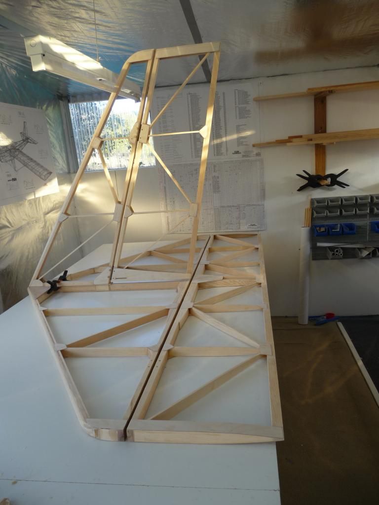
To give myself a bit of encouragement, I offered up the empennage to the fuse. At last it looks (a bit) like a plane! Then I fitted the fin/tailplane brace tubes.
Posted by: beragoobruce, March 15, 2015, 1:42am; Reply: 84
I added some additional diagonal members to the cockpit. These are to attempt some sort of 'crash cell' around the pilot, by providing a loadpath up to the main frame from the fuselage floor in the event of a very heavy landing. Also to act as panel breakers on the large slabs of thin ply sides, which I suspect would otherwise drum under vibration, making a noisy cockpit even noisier.
They may also offer a hardpoint to mount throttle, trim & flap levers later. (Yet to be decided on. . .)
Then I varnished the cockpit. This was messy, as I had to climb inside to get to the forward end of the floor & underside of engine bay. I hate varnishing!
Posted by: beragoobruce, March 15, 2015, 1:58am; Reply: 85
When the varnish was hard enough - which took a few days, even in my shop temp of 90+ - I fitted the seat & setback to let me sit in it & make suitable sound effects. :) :)
I made a mockup of the floor & rudder pedals, and played around with placement of rudder pedals and heel brake levers (not shown on pic). With this fitted, I found the seating arrangement very comfortable, and headroom enough to allow for a helmet if I decide to wear one.
Posted by: lake_harley, March 15, 2015, 2:07am; Reply: 86
I always enjoy your updates. Such beautiful, detailed work. It seems too that the lighting and shadows in your shop add dimension and beauty to the "furniture quality" build you are doing. Or, are you just that skilled a photographer too?
Looking forward to the next installment.........
Lynn
Posted by: beragoobruce, March 15, 2015, 3:01am; Reply: 87
Thanks Lynn!
My interweb connection disappeared, just as I was trying to post this last instalment.
I'll try again.
Posted by: beragoobruce, March 15, 2015, 3:17am; Reply: 88
The tail fairing with my kit was for a 1030, so didn't suit my build. Dave kindly sent me the piece of plywood I asked for as a replacement, as I prefer using wood to GRP when possible. My thanks to Gary Clare for sending this on to me - good on yer Gaz!
I extended a few of the turtledeck stringers aft of the rear former to support the thin ply fairing. I cut the slots for the tailplane & fin, extending them forward until the mounting holes aligned.
Later I will fit a radiussed dorsal fairing, but I'll do this after covering to maker the covering process easier.
Posted by: AirCab, March 15, 2015, 3:42am; Reply: 89
Yes, Yes, Yes ! Very Nice Work, and thanks for taking the time to take great pics, and documenting the build. This of course is great inspiration !
Steve
Posted by: Ricardo, March 15, 2015, 3:50am; Reply: 90
Best job I've seen in this forum so far.
Top quality work Bruce, but is time for you to watch the F1 race ;)
Posted by: beragoobruce, March 15, 2015, 4:21am; Reply: 91
Thankyou kindly!
Yes, it will be interesting to see who comes 3rd & 4th!
Posted by: Dick Rake, March 15, 2015, 5:55am; Reply: 92
Bruce,
I built mine 20 years ago and after seeing your beautiful work it makes me want to build another one. If you haven't figured it out yet, you will reach a point in the build where you really don't want to hide all that work with fabric. I'd be willing to bet that you find it hard to fall asleep at night because you just can't get that little sucker out of your head! Now that I think about it I'm awake at 2:am thinking about airplanes. Damn you Bruce! No more pictures, I need my rest!
Dick
Posted by: bigbrixx1, March 15, 2015, 2:36pm; Reply: 93
Outstanding as always Bruce. The v notches in canopy are brilliant! I will be incorporating them in my build also!
Posted by: beragoobruce, March 15, 2015, 8:29pm; Reply: 94
Thanks to both! And Dick you are of course right. I'm a Max saddo - it's what I think of falling asleep; when I wake in the morning, planning my day, and when I wake during the night I go back to sleep working out details.
My wife thinks I'm obsessive, but hey, it's cheaper than a mistress. . .
Bruce
Posted by: alex3, March 15, 2015, 11:17pm; Reply: 95
Hello Bruce,
I see in your older fuselage and recent pictures you have additional corner blocking and gussets around the not vertical Sta 2 and the seat diagonal. Do you have any closer pictures of them. I also am going to add the additional cabin diagonal. Figure it can't hurt.
I don't know about being cheaper than a mistress. Not that I have any experience, but those I know who do are always broke from spending on one or the other and worried about how to divide their time between the two. Kinda sounds familiar.
Alex
Posted by: steve.owen, March 16, 2015, 7:23pm; Reply: 96
great looking, now i have to go back and change mine, plywood looks so much better then clear plastic.
Posted by: beragoobruce, March 17, 2015, 3:05am; Reply: 97
Quoted Text
I see in your older fuselage and recent pictures you have additional corner blocking and gussets around the not vertical Sta 2 and the seat diagonal. Do you have any closer pictures of them.
Hi Alex
Have you looked at post 32 on page 2 of this thread? I think I put all the pix I had of the corner fillets/gussets in that post.
Unless I'm misunderstanding the area you're asking about?
Cheers
Bruce
Posted by: Arthur Withy, March 17, 2015, 8:14am; Reply: 98
Gidday Bruce,.... I see a Major issue with your build ??) ??) ??)
Its not in my workshop...LOL :P :P :P
simply put.....Bloody beautiful..... and I cant wait to see YOUR mistress finished
have you chosen a colour scheme.?
Best wishes Arthur
Posted by: beragoobruce, March 17, 2015, 12:21pm; Reply: 99
G'day mate - you've been quiet lately. All good?
Glad you approve of the build - how did you know I'd finished with my mistress? :)
I'm going to paint it white for starters, then think about what (if any) other additions to make. I'm not the dog's danglies at spraying, so anything I do will have to be simple. Plus by then I'm going to want to fly it, rather than spend even more time on my marathon build.
Are you still exercising the scarf?
Bruce
Posted by: alex3, March 17, 2015, 2:59pm; Reply: 100
The postsIamlooking aware 27,28 and 84.i am looking at the RS10 seat diagonal and the seat belt attach point and also you have a comer block on the forward side of Sta 2 RS8. In the later picture you have them covered with the gussets. I am also considering adding a small wood filler at the rest joint of the rS10 and sta 4. (This is at the "d" perspective of sht 1)
Posted by: alex3, March 19, 2015, 7:21pm; Reply: 101
Thanks Bruce, that's exactly what I wanted. I will have to get the UK directives and study them. I am just trying to do half a good a job as you and Brian(bigbrixx1) I look ant your pictures and try to improve my best. Thanks, Alex
I have a cousin in Perth. Someday I will get there.
Posted by: beragoobruce, March 19, 2015, 8:19pm; Reply: 102
Sorry, deleted the post. Here it is again, FWIW.
Sorry, I misunderstood the area you were talking about - got it now.
As regards the seat belt mounting point, there is a UK directive that a steel plate be used, which picks up 3 bolts, to distribute the loads.
I reckon this is overkill, but I wanted more than a single bolt in wood. So I added the diagonal to which you refer. It is RS10, and is bonded to the base longeron & the seat diagonal/short upright. See the attached pic. In this pic you will see the three holes which would take a large steel plate to cover. Hence my decision to only pick up 2 bolts, these being the upper one on the original upright, & the one on the new diagonal piece.
I will use a short length of 1"x 1/8" steel to make a strap picking up both of these holes. I will also bush the holes to increase the bearing area in the wood. The top bolt will have the seat belt fitting mounted to it.
The aim is to have this strap roughly in line with the direction of the seat belt, so as to align with both bolts. Not sure I got the angle right.
Regarding the small additional block on the forward face of station 2, I felt a bit of additional help to spread the landing loads would be a good idea. At that time, I didn't have the drawings for the steel u/c installation. When I got them, I found they called for quite a large RS10 block where my smaller one was. So rather than remove my original block, I cut an RS10 to graft onto it, then gusseted over.
Hope this helps. I will be posting pix of my seatbelt installation when completed.
Posted by: beragoobruce, March 29, 2015, 12:59am; Reply: 103
Just one more photo I forgot to add. It is showing that unlike the plans, I glued the cleats supporting the turtledeck stringers on the aft side of the fuselage frames.
This was purely for cosmetic reasons (it won't affect the strength or anything). Just I think it looks less cluttered when you look down the fuselage from the baggage bay.
Bruce
Posted by: beragoobruce, March 29, 2015, 1:05am; Reply: 104
And so to the undercarriage.
I went for the Eros kit partly because it included the ready-made steel gear, which I prefer. I mounted this on the fuselage ok, then trial assembled the wheels onto the stub axle.
Then I found I had a big problem. The gear had been supplied with the stub axle cut at least an inch too short, such that when the wheel was in place, there was no axle left protruding to attach the wing pickup to.
Posted by: beragoobruce, March 29, 2015, 1:36am; Reply: 105
I contacted Dave Cooper on this problem. His solution was to cut back the outer bearing to clear the necessary axle length.
However, since the bearing is under an inch long, it worked out that with the wheel assembled in its correct position, with the large washers fitted each side, and the inner spacer machined down to give minimum clearance for the drum brake backplate bolts, the bearing would have to be reduced to 7/16" width.
I was not happy with this solution. It seems to me that such a narrow bearing would wear much more quickly than the full width version. And more importantly, in wearing it is possible it would reduce the wall thickness of the axle - which of course supports the major wing loads.
So in the absence of a new set of steel legs, I decided to machine the Azusa hub deeper to recess the bearing as far as possible. I don't have a lathe in my shop, but I was lucky enough to find a good ole boy in my local town who works as an agricultural engineer. I got chatting to him, & he very kindly let me use his enormous, solid, ancient lathe for me to do the job.
So I bored the outer hubs to the same diameter, and left about 1/8" shoulder on the inside face for the bearing to sit against. This left about 3'16" of bearing protruding from the outer hub face. I machined this off, leaving the bearing face just proud of the hub.
This way, I still have most of the original bearing bush length, and I have 0.91" of axle sticking out on which to fix the wing pickup. This means I'm going finish up with 1.82 dia edge land for the wing pickup 1/4" bolt, which whilst is not as much as I'd like I hope will be adequate. If not, guess I'll find out the hard way. . .
So if you have steel gear not yet fitted, measure the stub axle protrusion. Mine was 4.5" (from memory), but I believe it should be 5.5".
Posted by: beragoobruce, March 29, 2015, 1:48am; Reply: 106
I'm working on my pushrod control system now.
I made the drawings for this before I got the kit, but I reckon to do some of the key parts in plywood as a trial installation to check my geometry, travel, clearance, etc.
But here's the first parts. They are the idler that lives under the seat for the elevator pushrod, and the double elevator horn. Just in case anyone has noticed, the section view of the elevator horns has been revised, so doesn't reflect the 'production' version.
more later. . .
Bruce
Posted by: pkoszegi, March 30, 2015, 7:52pm; Reply: 107
I wish I would have the third of your wood working skills. Amazing.
But you grow out your garage so slowly you need to build your hangar :)
Posted by: beragoobruce, March 30, 2015, 9:20pm; Reply: 108
Swap you for a third of your mechanical skills Peter! And yes I have a real estate problem. . .
Posted by: bigbrixx1, March 30, 2015, 10:56pm; Reply: 109
Nice work as always Bruce! Although I am going with the teleflex cables.....UK style with double elevator cables. I am intrigued by your setup. Cannot wait to see more of it!
Brian :)
Posted by: beragoobruce, August 1, 2015, 12:11am; Reply: 110
I see it is 4 months since I last updated this thread. That may be a relief to some!
I have been taking a bit of time out from my build to do family stuff. Part of that time was spent on the project pictured, for my little grandson Tom, also pictured. (The bike was to keep him happy when mummy came home with a new little sister for him. . .).
The rest of the time I've been doing a myriad of small detail fiddly bits. Trim tab; baggage bay; wing root fairings; instrument panel, etc etc. Now I understand the expression "90% complete, 90% to go". So true!
I've also attached both wings, and fitted the struts.
The bulk of the time, though, has been spent researching which engine to buy. It seems the elderly Rotax 503 I have is not worth a rebuild, so I need an engine. I checked out several, and shortlisted the Rotax 582 and the Compact Radial Engines MZ 202.
Both make more power than I need, but great to have a few horses waiting in the wings (?) in case I need them. I was going to go with a 45 hp MZ 201 with belt drive, but that engine would need a lot of cutting & remaking of the Eros cowling. Plus despite moving the engine as far forward as possible, it is so light I would still need to add about 20lb ballast at the nose (though I've had to make some guestimates on my c.g. position with the 503 to work that out, & I may well be wrong).
In the end I've ordered a 60 hp MZ202, as it is a very similar size & envelope to a 503, needing few structural or cowling mods. And the Rotax is liquid cooled, so I'd have to faff with mounting a radiator, with even more cowling mods; the 582 is very heavy; and anyway Rotax have enough money without me giving them any more. I'd rather Leon had it:)
The MZ202 looks a great engine: it's fan cooled, big (626cc), lazy, high torque - and all those Mosquito helicopter pilots flying in front of them can't be wrong!
So I've also spent a fair bit of time on designing the propeller to go with it. I've finally decided on a 3 blade prop, 62" dia and 42" pitch. There is some scope to modify this in light of flying experience, but the scope is limited being a hand carved wooden prop. I've also been looking into sources & types of wood. I'll probably use Victorian Ash & Queensland Maple laminates. But all this for a future thread. . .
I'll post in more detail on some of these adventures, and I'll start with the instrument panel as Reto is thinking about his now.
Cheers
Bruce
Posted by: Reto S, August 1, 2015, 2:18am; Reply: 111
Hi Bruce
That cute bike should go in mass production!
Great to have you back...
Cheers
Reto
Posted by: beragoobruce, August 1, 2015, 3:39am; Reply: 112
Thanks Reto! But it wouldn't be fun to make them for a living. . .
In reply to your question on instrument panel a/v mounts, I think it is worth making an effort to isolate all those expensive items from the high frequency vibration from our 2 stroke engines. And just maybe from some heavy landing shocks!
I used some very soft neoprene rubber mounts - I found them on ebay.
Posted by: beragoobruce, August 1, 2015, 3:44am; Reply: 113
I made my panel from the offcut of the ply used in the cockpit so it would match in appearance. Except I used several coats of matt varnish to be anti dazzle in the sun.
Because the ply is thin, I used some spare 1.5mm ply to stiffen it up, but still save weight. I epoxied the mounting lugs onto the back of the panel.
Posted by: beragoobruce, August 1, 2015, 3:47am; Reply: 114
Then I needed to make some hard points for the upper mounts. The lower mounts just sit on the fuse decking.
Posted by: beragoobruce, August 1, 2015, 3:53am; Reply: 115
Here's a pic of the partly completed panel. It's a bit tight getting everything in, but I have all the instruments I need in there.
I'm starting with the through mounting bolts only just deforming the rubber mounts. This gives minimum stiffness. If the panel moves around too much, I can just keep tightening the nuts to load up the mounts until I get the right compromise.
Posted by: beragoobruce, August 1, 2015, 4:01am; Reply: 116
And finally the pilot's eye view. I have biased the instruments toward the top of the limited panel space to leave room to fit the electrical switches along the bottom.
I may use a pedestal compass mounted on the upper coaming, and use the spare hole for a small analogue tachometer, depending how I get on with the TinyTach.
Finding room for a radio & GPS is a bit tricky, but that's tomorrow's problem. Or more accurately, next year's! I also decided to leave out the VSI, as I'm not sure that instrument can really justify its piece of very limited real estate on the panel.
Posted by: bigbrixx1, August 2, 2015, 4:56pm; Reply: 117
Thanks for the updates and photos. I am starting to layout instruments and you have answered a bunch of question for me! Great work as always!
Posted by: beragoobruce, August 5, 2015, 6:06am; Reply: 118
I am keen to reduce drag wherever possible on my plane, and one area that will help is fairing the wing roots. In particular, the gaps at the leading & trailing edges.
Ideally. I'd go for a 2" or 3" radius fillet to smooth the airflow, but this isn't really practical on the Max, so I've just made them as big as I can. Even then the starboard fillet covers some of the canopy hinge.
I started when the wings were attached. First I stuck a wide strip of brown shiny parcel tape all round the root so that any stray epoxy wouldn't permanently bond the wings to the fuselage :-/. Then I cut some thin strips of card & stuck them in place with double sided tape. I butted them up to the fuse & used 2 layers. This is to give a little clearance between the wing & the fairing so as not to jam the wing during rigging/derigging.
I cut some spare 1.5mm birch ply about 3/4" wide so that the grain was crosswise to facilitate bending around the L/E. Again, I temporarily stuck this to the cardboard strips with light duty d/s tape, and bonded them to the fuse with WEST.
To fill in the giant gap at the trailing edge (where the fuse starts to curve away), I made fairings from 3mm poplar ply. I infilled the aft portion up to the aileron horn with a vertical web. I had to fit ply between the aft main bulkhead and the first frame to support these rear fairings. Also to give a land for the fabric around where my aileron pushrod exits the fuselage.
Posted by: beragoobruce, August 5, 2015, 6:37am; Reply: 119
I made 2 formers from ply with a small & then final radius for shaping the fillets. I mixed up the WEST epoxy and worked in huge quantities of 410 Microlight low density filler.
You mix in sufficient to form a really really stiff paste, and then apply it over the area to be filled. Because the paste is almost dry, I wet both surfaces with neat epoxy as usual. I formed it with the smaller radius tool, & let it harden.
The next day I repeated the exercise with more WEST/410 filler, using the large radius tool.
When that had hardened, I sanded the fillets to final shape & surface finish. Finally, I will seal the fillets with a coating of neat WEST. This makes them very hard & able to take whatever else is applied (paint; glue; fabric etc).
The WEST + 410 Microlight is an excellent filler. It is very low density, does not slump even when laid on thick, sands very easily to a great finish & is a hard surface after the last epoxy coat.
Posted by: beragoobruce, August 5, 2015, 6:43am; Reply: 120
Now it's easy to see where to put the wings when I'm rigging!
Posted by: pkoszegi, August 5, 2015, 6:46am; Reply: 121
Bruce, you always amaze me with these details.
If you are near to install your engine and thinking about your instrument panel, send me a PM . If you are interested I will work out a very special price on the instrument electronics. I need a reference in Australia.
Peter
Posted by: beragoobruce, August 5, 2015, 6:53am; Reply: 122
Thanks, Peter, both for your kind words & your offer on the instruments. I have pm'd you.
Bruce
Posted by: aeronut, August 5, 2015, 1:21pm; Reply: 123
That is really great the way you have done the fairing. I have often wondered about the effect of fairing this area; it has got to be positive and I suspect quit significant. Thank you for the post. :)
Posted by: beragoobruce, September 7, 2015, 2:43am; Reply: 124
I decided to fit differential brakes, since it seems worthwhile to do a bit extra to acquire a bit of help on low speed taxiing if you're going to fit brakes anyway. And I don't really like the idea of a single brake lever mounted on the stick.
I went for heel brakes over toe brakes, because a) the space is a bit limited above the pedals for a separate brake area and b) heel brakes are easier. I expect to get used to their operation during all my ground handling, & high- & low-speed taxi trials. If not, I'll change them.
I made the pedals from 2.5" x 2.5" x 1/8" angle, with a nice radius root. The hinge was just a heavy duty hardware store item. I decided to terminate the cable at the brake pedal with an eye fitting because it's too hard to reach down there to adjust the cable length, & I have adjustment at the wheel end. I put light springs on to hold the pedals against a wooden stop. I may make an aluminium cover for the cable end as it looks a bit untidy. Or maybe not!
In order to determine the optimum position for the ergonomics of the pedal operation, I made an accurate wooden mockup of the rudder pedals & the brake pedals on a dummy floor. I sat on a box & positioned the rudder pedals as they are in the plane. Then I played around with different placement for the heel brakes. Best for me came out as shown in the pic.
At the brake arm end, I made a fitting from a 10mm s/s bolt. I drilled through the centre & tapped it to take a 4mm bolt. I drilled through the head to allow the brake cable to pass through, and tightened the centre bolt to clamp the cable. I locked it with a plain nut. The 10mm bolt has washers each side of the brake arm, and a nylock nut adjusted to permit rotation but minimum slop.
I fitted an outer cable adjuster to a small angle bracket as per plans.
Posted by: Tom, September 7, 2015, 1:30pm; Reply: 125
The wing root fillets can indeed reduce drag substantially. The amount is calculable. See Hoerner's "Fluid Dynamic Drag" for how to calculate it. You need an estimate of the speed of the aircraft and the length of the wing chord and from there the calculations are very simple.
There are two types of drag that this filleting can reduce, but in this particular case where the wings are close to 90 degrees from the fuselage the really important type is called "interference drag". What happens with a "hard" unfilleted inside corner is that the boundary layers of the two surfaces are meeting at an angle to each other. Therefore they "interfere" with each other's flow and "trip" the flow into severe turbulence. The amount of drag at a hard corner like this when calculated out is quite significant. Adding a generous fillet allows each boundary layer to bend toward the other until they are meeting as though they were flow on one surface.
While the calculations given for this are pretty "fuzzy" the answers will be in the right ballpark and will allow some pretty good estimates of improvement in speed if you've precalculated the actual drag in flight. Conversely it can also give a good estimate of reduced fuel consumption.
It is worth mentioning that filleting at the roots of empennage surfaces, strut to surface intersections, landing gear to fuselage intersections, etc can all benefit from fillets to reduce interference drag.
Tom
Posted by: Ricardo, September 7, 2015, 3:31pm; Reply: 126
Bruce:
I wonder if your design has enough cable travel to exert enough pressure on the drums.
I have the Azusa brake system hand operated, and is far from perfect. The drum have some little offset to the center axle and it needs quite a travel to tight the brakes. With only hand brakes I can keep the plane stopped at 5000 rpm maximum. At higher rpm it starts rolling.
WIll like to change to hill brakes to get tighter turns on my runway.
Posted by: beragoobruce, September 8, 2015, 8:12am; Reply: 127
Thanks for the input to both Ricardo & TTT.
I will look out for the potential problem you raise, Ricardo. I am expecting to take up the slack by re-adjusting at the brake arm after a bit of bedding in of the brake linings. If there is insufficient travel available at that time, I will either move the cable further up the heel lever, or shorten the brake lever as per TTT's suggestion.
TTT, I made my own fittings because the cable stops I bought were clearly meant for a throttle, and the tiny little screw in them didn't look to be strong enough to take a frightened man standing on the brake pedal.
It is hard to assess the required travel before actually using the system. Similarly, the amount of pedal pressure needed for the brakes to be at all effective (which of course will be affected by the length of the brake arm). So your inputs are appreciated: I'll let you know how it goes in the field.
Bruce
Posted by: NowraSteve, October 7, 2015, 5:02am; Reply: 128
The trickier bit was the "closing web" for the rear spar.
Hi Bruce,
Going back a ways, if I may, to this post...
Question: How did you control the alignment of the sanding disc relative to the centre target point of the ribs? Particularly how did you ensure that all the ribs were the same? Just careful eyeballing and a steady hand? Did the sanding wheel tend to track to the same centre because the rib gussets were all carefully cut to the same length?
Simply stunning build BTW! So please excuse me as I contemplate copying as much as possible ;D (within my very limited limits).
Steve.
Posted by: beragoobruce, October 7, 2015, 10:29pm; Reply: 129
Thanks for your kind words, Steve.
To sand the rear spar ribs to fit the closing web, I did this by hand. If you look much earlier in my thread, when I made the gussets located at the rear spar, I modified their profile to form an arc about the pivot point of the aileron hinge.
Then when sanding with the gadget as shown in your quoted pic, the device just automatically centres where it should.
After initial sanding, I strung a chalk line the full length of the rear spar, at several positions around the closing spar area. This showed up high points or out of line areas, which were sanded down.
You need to allow quite a generous clearance between the aileron nose skin & the closing web trailing edge spars, because there will be two thicknesses of Dacron +glue + paint. And to allow for a bit of wing flex in turbulence.
Bruce
Posted by: lake_harley, October 8, 2015, 1:01am; Reply: 130
Regarding the gap between trailing edges of the wing and the aileron nose skin, I was advised to leave about 3/32" gap when I was to that point in construction. Since the gap varied a slight amount when the aileron was moved through it's range of motion, I checked for that clearance while moving the aileron and checking the clearance. It worked out OK once everything was covered, so I'd say I got good advice. Regarding Dacron Bruce, I did a single layer wrap around the aileron leading edge and did the cloth overlap at the trailing edge....ie: I started the cloth on the top of the aileron trailing edge (about 1" or so), wrapped around the bottom of the aileron, over the top and used a pinked edge then on the underside of the aileron trailing edge to finish it off. That gave a total cloth overlap of about 2". Maybe you were also referring to the cloth wrapped around the top and bottom trailing edges of the wing? I just thought of that possibility as I was about to hit "Post Reply" :B
Lynn
Posted by: beragoobruce, October 8, 2015, 1:21am; Reply: 131
Hi Lynn.
Yes, I meant the underside of the upper & lower trailing edges, plus the cloth wrapped around the leading edge 'nose' of the aileron. I've edited my post to try to make this more clear. Thanks!
Bruce
Posted by: beragoobruce, November 29, 2015, 12:56am; Reply: 132
The last few weeks I've been finishing off all the small jobs on my fuselage. This has taken a lot of time, & it's easy to start thinking I'll never get finished. But I have now almost got to the end - I think. I have the engine installed, and the fuselage is rolling on its wheels. So I must be nearly there!
One of the fiddly bits was the baggage bay. It seemed to me there was a lot of empty space behind the main bulkhead (aft end of cockpit), which is close to the c.g. & could therefore be useful for carry bulky, if not heavy, items. I'm thinking sleeping bag, tent, jacket, etc for when I fly away from home. I will need to establish - and placard - the safe weight I can carry when I do my weight & balance.
I made a 3mm poplar ply infill for the main frame, the upper portion of which was the access door. I stiffened the two panels with 1" ribs epoxied behind them, & mounted the hinges behind the door to conceal them.
I made a couple of barrel bolts from 1/4" dia aluminium rod to keep the door shut, and glued a bit of RS9 across the area where my head is to provide some whiplash support in case I reverse into something solid at high speed. The forward face of the door will carry a padded headrest in due course. The crosspiece engages in a couple of housings bonded to the rollover hoop sides.
I put in an additional diagonal at the baggage bay floor level, making an 'X' shape support for the floor. The floor itself is 3mm poplar ply. I screwed this in place, so that it is removable. Then I made some small ally clips to provide anchor points for a cargo net. (I have used these cargo nets on my motorbikes, & it is surprising how good they are at holding stuff, even at unfeasibly high road speeds.)
I exited the seatbelt shoulder straps at the height they naturally want to be relative to my shoulders, so the baggage bay bulkhead is not taking any load in a crash. what limited stuff I carry can fit mostly under the belt straps.
I still wanted to be able to visually inspect the rear fuse, but I didn't want to have a gap under the frame in case baggage came adrift & fell into the rear fuse. So I fitted a Lexan infill to, well, fill in this space. The 3mm bolts in the pic are temporary, I will replace them with button heads when they arrive from Hong Kong.
So here's the pix:
Posted by: beragoobruce, November 29, 2015, 1:23am; Reply: 133
One more showing the canopy frame in place & the baggage door open
Posted by: beragoobruce, November 29, 2015, 1:52am; Reply: 134
I've posted elsewhere about my engine, but it rightly belongs in this thread. So please forgive any repetition.
I bought the Eros kit intending to use a Rotax 503, but then found the old model I had was not worth rebuilding. After much research & thinking about which way to go, I bought a new MZ 202 from Compact Radial Engines in Canada. Leon Massa (main man) is very helpful, and makes a superb engine. I weighed it next to the 503 and it is 22lbs lighter - and that includes electric start. and it is 60h.p. conservatively.
It doesn't drop straight in to the engine bay. The fan is direct drive, & quite a large diameter, so this forms a step that extends below the level of the mounting feet/engine bay floor. This meant I had to make a cutout in the floor, and a cover which screws in place to seal off the engine bay from the cockpit.
The other major difference is that the 202 uses reed valves, unlike the piston porting on the 503. The reed valve arrangement requires the carburettors to be at crankshaft level, or some 4" lower than the Eros cowl is designed for.
I still wanted to enclose the carbs, so I made an extension to the port lower bulge on the standard cowl. I found some thick plastic pressure elbows in the plumbing department of my local hardware store, & with a bit of fettling these provide a means of getting the air filters in an upright position within the standard cowl. The lower minicowl addendum won't be too noticeable when the final paint is done - I hope.
Other than that, the engine fits well in its designed space. Because it is so much lighter than a Rotax 503, I bought a fairly large battery, and mounted it as far forward as I could. It needed to be at an angle to fit in forward of the nose bowl, so I bought a sealed battery that can be used in any position (even upside down, though I hope never to find out whether it still works in that configuration).
I was a bit concerned about the airflow from the exhaust manifold being sucked into the cooling fan inlet, so I modified the standard aluminium baffle by adding a scoop. This almost abuts the exhaust face of the cylinder, & is swept back to encourage the backwash of hot air from the manifold Y piece to exit from the stbd cowl bulge rather than the fan. I have made additional cutouts in the cowl to allow the airflow coming in to exit, because although there are 5 cutouts facing forwards to allow air in, there is very little provision for the air to get out. But I will post some pics of the cowl later. And with at least 60 hp under the cowl I want to let all that heat out.
Early last week I rolled out the fuse & fired up the engine. I was very pleased with how well & smoothly it ran. Youtube link here:
https://www.youtube.com/watch?v=MJ1AppoTblw&feature=youtu.be
Posted by: beragoobruce, November 29, 2015, 1:55am; Reply: 135
Posted by: beragoobruce, November 29, 2015, 1:56am; Reply: 136
Posted by: aeronut, November 29, 2015, 12:12pm; Reply: 137
In the video of the engine run it appears that there is a clutch between the prop and gear box, is it a feature of the gear box?
Posted by: beragoobruce, November 29, 2015, 12:32pm; Reply: 138
Yes, it's a centrifugal clutch before the gearbox. It stops gearbox chatter at tickover - works very well.
Bruce
Posted by: beragoobruce, November 29, 2015, 12:33pm; Reply: 139
And it also means you can practice proper deadstick landings. Fun!
Posted by: aeronut, November 29, 2015, 4:29pm; Reply: 140
Yes I think that is a good feature. I start my 447 and idle it at about 2000 rpm but throttle all the way down as I get in and I think that must be hard on the gear box so I idle it right back up after getting seated.
Posted by: PUFF, November 30, 2015, 4:20pm; Reply: 141
Be very careful with that LUGGAGE compartment.
You can easily get your Weight and Balance out of kilter and make a huge mess..
Posted by: beragoobruce, November 30, 2015, 7:29pm; Reply: 142
Thanks for your concern, Puff. I realise it's a temptation to overload, that was why I said in my original posting that I will need to establish a safe weight when I do my weight & balance trials. And to placard the max weight that keeps me within allowed c.g.
But without a baggage bay, where do you carry things like a tent & sleeping bag? Light but bulky items.
Bruce
Posted by: stevejahr, November 30, 2015, 9:47pm; Reply: 143
The other way to insure the fan does not suck up hot air... is to provide an intake duct to the fan. Although the metal duct/cowling around the exhaust makes a lot of sense.
Posted by: beragoobruce, December 1, 2015, 10:24pm; Reply: 144
Here's some photos of my elevator trim & control in the cockpit. On the trim control, the knob at the bottom of the quadrant is both handle & locking device. You unscrew 1/4 turn, move along the quadrant, & tighten up. I will add some markers for takeoff & landing settings after I fly.
Also a photo of my throttle control. This time the locking knob is in the centre. But the carburettor springs were too strong, so I added a bungee on the lever to reduce the force needed for the lock to hold better under vibration.
Bruce
Posted by: PUFF, December 3, 2015, 12:20pm; Reply: 145
Shoudn't the spring on the trim tab be on the bottom?
Posted by: texasbuzzard, December 3, 2015, 1:16pm; Reply: 146
I believe the setup Bruce has is correct as the trim tab will always be in the down position. the force will be on the cable not the spring.
monte
Posted by: beragoobruce, December 3, 2015, 9:11pm; Reply: 147
I'm not sure it makes a lot of difference as regards function. I put the spring on the top for two reasons.
Firstly, if the cable breaks, or the friction device loosens, the tab will make the elevator go down, which means the plane will go into a dive while my ancient brain figures out what went wrong. I'd rather this than a sudden nose up.
Secondly, I was able to exit the cable via the elevator pushrod tube, which means there is less bending on the cable outer as the elevator moves up & down. It also makes it all a bit neater.
Of course I may be missing something, so criticism welcome.
Bruce
Posted by: beragoobruce, December 3, 2015, 9:20pm; Reply: 148
Quoted Text
The other way to insure the fan does not suck up hot air... is to provide an intake duct to the fan. Although the metal duct/cowling around the exhaust makes a lot of sense.
True, but there is an inlet duct of sorts in the Eros cowling. It is an inlet towards the aft end of the cowl, & positioned such that the outside air feeds the fan.
My metal shroud was just to inhibit hot air reaching the fan.
Posted by: aeronut, December 4, 2015, 1:31am; Reply: 149
I noticed that the exhaust manifold springs are bare. You will probably pass a piece of safety wire through the center of the spring connecting the two parts of the exhaust manifold together and I applied a line of hi temperature silicone along the length of the spring, I am told it helps with the vibration of the spring and the wire helps to hold the spring parts on to the engine should the spring break. I have had one spring break on my Max. I do realize that you were only running up the engine to see if sounds like a Merlin (lol) but I would do this before the first flight. ;)
Posted by: beragoobruce, December 4, 2015, 2:14am; Reply: 150
Thanks, Aeronut - good points. I will be sure to safety wire them before I commit aviation!
Puff, I'm still concerned about your comment on the trim tab spring position. Can you say why it should be on the bottom? Thanks.
Bruce
Posted by: PUFF, December 4, 2015, 12:38pm; Reply: 151
I guess it depends on how gentle that dive will be?
Posted by: Bob Daly, December 4, 2015, 2:23pm; Reply: 152
The trim tab setup looks fine to me, I would just suggest a stop or some other scheme to limit or prevent "down" trim.
Posted by: stevejahr, December 5, 2015, 1:14am; Reply: 153
For the cable configuration the spring is where it has to be. The cable is in a pull-pull configuration so it needs the spring to create the other pull.
Now if the cable breaks or comes apart... there is going to be a LOT of down and the pilot is going to have to be pulling very hard very quickly.
How well does a 'max do in an outside loop?
Posted by: beragoobruce, December 5, 2015, 2:34am; Reply: 154
True - but the alternative is a sudden very strong nose up pitch.
Of the two, I'll take the nose down.
Bruce
Posted by: Ricardo, December 5, 2015, 4:28am; Reply: 155
That won't happen if you put a restraint on the trim travel, so if the cable breaks it won't have a drastic effect on the plane attitude.
Posted by: beragoobruce, December 5, 2015, 5:11am; Reply: 156
Yes, good idea. I can limit the travel with a short cable between the lower horn & the cable bracket. Sorted!
Posted by: PUFF, December 7, 2015, 12:50pm; Reply: 157
yes, if you can fix it so that a gentle up or down then it might not be so bad.
Posted by: beragoobruce, December 20, 2015, 10:27pm; Reply: 158
I think I have finally finished the airframe, ready to cover. So yesterday I wheeled the fuselage outside, & carried all the other loose bits out. I found a shady spot under some trees (it was 95 degrees in the shade outside. And 104 in my workshop) to assemble the bunch of bits.
It all went together reasonably well, though some of the rigging pins & bolts were a bit reluctant to go in. I wouldn't like to rig every time I go flying.
I noted any problems, & got my mate from down the road to look over it for anything obvious I might have missed before I cover it all. As has been said on this forum, after all that work it seems a shame to cover the wooden bits - they look really nice naked!
I took some photos, see below. It's not a good background, but better than being out in the sun. Then I tore it all down again, put it back in the shed, & walked away until after Christmas.
Next step covering - Oh joy :-/
Bruce
Posted by: beragoobruce, December 20, 2015, 10:31pm; Reply: 159
Posted by: beragoobruce, December 20, 2015, 10:34pm; Reply: 160
Posted by: beragoobruce, December 20, 2015, 10:36pm; Reply: 161
Posted by: Ricardo, December 20, 2015, 11:46pm; Reply: 162
Congratulations! Great craftsmanship, you'll enjoy the covering as well.
Throttle on the right hand side. Is that because you guys drive on the left hand side? Just being curious.
Posted by: aeronut, December 21, 2015, 12:56am; Reply: 163
She looks like its time for the feathers. Cause that is what you built her for FLYING. Save the pictures cause in five years they will be priceless. ;)
Posted by: beragoobruce, December 21, 2015, 1:23am; Reply: 164
Thanks guys!
Ricardo, I put the throttle on the right hand side because I am left handed, & I prefer to use my left hand on the stick. One of the advantages of building a personal plane :)
Bruce
Posted by: lake_harley, December 21, 2015, 1:27am; Reply: 165
What a shame that wild dingo's stripped all the fabric off of such a pretty airplane! You know I'm just joking. ;)
Now I'm NOT joking....it looks GREAT. As pretty as MiniMAXs are "naked" I can't wait to see it covered.
Lynn
Posted by: Arthur Withy, December 21, 2015, 3:57am; Reply: 166
absolutely Lovely work Bruce 8)......and I want more photos not LESS...LOL. ??)
Good work on the throttle...I figured your were Left handed before I saw the responses. :o
what colours are you choosing Bruce..?
regards Arthur
Posted by: pkoszegi, December 21, 2015, 6:21am; Reply: 167
Bruce its lovely ! This piece of art make sense to cover it with transparent material. You would be the first who can see thru the wings.
Posted by: beragoobruce, December 21, 2015, 7:07am; Reply: 168
I appreciate your appreciation, Lynn, Arthur & Peter - it's great to have encouragement when you're working alone without any kindred spirits in the flesh.
Arthur, I'll have to go with mainly white to reflect the hot Aussie sunshine. I would go silver but some bugger has already done that ;D
I want to go for the retro look as I see the Max as a traditional type plane. I'll add some contrast colour - maybe blue. A trawl through some old taildragger pix may give me some ideas. I loved the look of that midnight blue Max at your toy run, but I'd be too worried about heat soak softening my glue :o
Peter, I'd love to cover the wings with Mylar, mainly to improve the downward visibility for watching the wildlife. That's the advantage you have with your HiMax.
Bruce
Posted by: Reto S, December 22, 2015, 1:51am; Reply: 169
Hi Bruce
We need more pictures before you cover her, I agree! :)
Great achievement!
I can't wait to see her taking you up in the sky!
Cheers
Reto
Posted by: stevejahr, December 22, 2015, 5:06am; Reply: 170
Very nice Bruce, Airplane porn for sure!
Posted by: Arthur Withy, December 22, 2015, 2:34pm; Reply: 171
well silver aircraft do FLY well....also I love Larry Vetters double blue and white minimax. Drop him a line Im sure he will send you heaps of photos on request.
Ohh Pauls Minimax I think is left over paint from the Smithys replica southern cross....see photo...Now Blue and silver is also nice and classic
regards Arthur
Posted by: beragoobruce, January 9, 2016, 3:15am; Reply: 172
Now that I'm getting a bit nearer First Flight (though it's still a way off :() I've joined my local flying club, started flying again, & got a space reserved in their hangar.
That made me think about the need for other pilots having to move my little plane around to get theirs out, & hopefully put it back in.
I'm a bit concerned about non-ultralight pilots giving my little baby a hard time, for example lifting by the tailplane (horizontal stabilizer) to move it around.
So I made some detachable handles, which I'll leave in place when I put the Max to bed, and add some placards saying "no lift" on the tailplane & "lift here" near the handles.. It might just save some clumsy/thoughtless person putting his fingers through the Dacron.
I made a hard point just forward of the tail, where there is already a 1/8" crossmember. The cleats are from 1/4" ply, with a 1/8" ply doubler on the inside face of the ply longeron. A short length of 1/2" dia ally tube is epoxied to these brackets.
The handle itself is a 5" length of 3/8" dia ally tube that is a nice fit inside the fixed socket. I tapped this M8 & fitted a short length sawn from a bolt & Loctited in place. The tubing is all spare from my build.
If 3/8" diameter seems a bit skinny, this was deliberate. It will start to bend before excess loads are fed into the aircraft structure proper, but should be adequate for light ground handling.
Incidentally, in the 3rd pic you can see a test piece of dummy wing structure I made for practice, both for heat shrinking the Dacron & later for rib stitching. I'm calibrating my iron at the moment, checking temperature ranges for the markings I've added.
Posted by: beragoobruce, January 9, 2016, 3:19am; Reply: 173
For flying away from my local field, I'll keep the handles in a little box I made that mounts to the bulkhead behind the seatback. I will keep various small light bits & pieces in here: measure for 2 stroke oil; spare plugs; some Castrol TTS, minimal tools etc.
Posted by: aeronut, January 9, 2016, 11:31am; Reply: 174
You are a very thoughtful, consecrate man. I really like your work with the airplane. Hope all goes well for you in the community hanger.
Posted by: fiebichpv, January 9, 2016, 2:48pm; Reply: 175
Outstanding craftsmanship, attention to detail and finish of all your airplane parts. Your photography is dead-on sharp and inclusive. I have enjoyed reading about your project as well as the comments others have made. I am in awe of your workmanship and ability to explain in detail what you are doing and why you do things in a particular way. Keep it up.
Paul Fiebich
Posted by: beragoobruce, January 11, 2016, 1:58am; Reply: 176
Thankyou Gentlemen (but it is only a lifting handle!)
I posted because there isn't much on builds at the moment on the board (although Brian is doing a superb job on his covering & painting). I hope Reto will be back soon to inspire me.
Paul, I use an old Panasonic Lumix TZ5 'point & shoot' camera that I've had for 7 or 8 years. But it's always been a great little tool. Glad you're enjoying my story :)
Bruce
Posted by: Dick Rake, January 11, 2016, 3:56am; Reply: 177
Thankyou Gentlemen (but it is only a lifting handle!)
I posted because there isn't much on builds at the moment on the board (although Brian is doing a superb job on his covering & painting). I hope Reto will be back soon to inspire me.
Paul, I use an old Panasonic Lumix TZ5 'point & shoot' camera that I've had for 7 or 8 years. But it's always been a great little tool. Glad you're enjoying my story :)
Bruce
Here's a picture of the way I did mine. A 1" aluminum tube that I insert through a fiberglass tube mounted in the fuselage. So far I haven't forgot to remove it before take off.
Posted by: Arthur Withy, January 12, 2016, 12:33am; Reply: 178
I usually find with shared hangars its not other Hangar mates that are the issue, because the respect is a two way street...its their friends or children who know nothing of aircraft...who try to sit on the 'tail' when unsupervised.
I leased space in my hangar for 10 years.....so I have the tee shirt....LOL
Simple rules and boundaries are the solution with good 'PILOTS'...but TTT we could use a hidden camera...LOL
cheers Arthur
Posted by: beragoobruce, January 13, 2016, 9:20am; Reply: 179
Quoted Text
For ME, the idea of having my Max in a community hanger would keep me awake at night
Well, it's not ideal. I'd rather have my personal hangar on my own strip. But that's not going to happen this lifetime. . .
So the local flying club is next best option. It has a 5700' asphalt runway, & a 5600' grass strip. I will be one of 3 planes in a hangar. There is a nice little clubhouse on the airfield. It is a 30 minute drive from my house. And with unlimited takeoff & landings, it costs me $20 per month. (That's Australian dollars, so about 14 of your American dollars.)
So I guess I'll just have to live with it :)
Bruce
Posted by: bigbrixx1, January 13, 2016, 12:33pm; Reply: 180
20 dollars a month! thats awesome!!!! The build is looking great! Question....How did you run your rudder cables? The plans show metal angle brackets about 5 1/2 inches ahead of horizontal stabilizer bolted to fuse side frames. Problem they seem to conflict with turtleneck stringers.
Thanks as always for your help
Posted by: beragoobruce, January 14, 2016, 7:36am; Reply: 181
Brian
I've had a good look through my plans, & have to confess I can't find any metal brackets where you describe. Do you mean the mounting brackets for the horizontal stabilizer? If so, these are nowhere near my rudder cable runs. Or turtledeck stringers.
I've attached a couple of pics of how my cables are arranged. They pass through F6 & then out through my plywood tail fairing. (The metal bracket in the first pic is supporting the elevator trim tab cable, so isn't shown on the plans)
Sorry, this probably isn't helpful. Can you photograph the area of the plans you're referring to?
Cheers
Bruce
Posted by: bigbrixx1, January 15, 2016, 1:20am; Reply: 182
Thanks Bruce! That's the way I will run them. I am glad your ahead of me with install. I can glean some of your great ideas! Keep up the great work!
Posted by: beragoobruce, January 15, 2016, 2:01am; Reply: 183
No worries. I'm about to begin covering & I've read your posts on this several times. Mutual help is what this forum is all about!
Posted by: beragoobruce, January 29, 2016, 2:42am; Reply: 184
I was going to leave things like fairings until after I'd flown, but being realistic about it, I realised if I did that it probably wouldn't happen. So I've faired my main struts, and hope to do likewise with fin supports & steel u/c diagonals concurrent with covering.
I thought about several different ways of fairing the very draggy struts. My preferred option was to use 1.5mm ply, soaked in ammonia to get a 1/4" leading edge radius, and wrapped around & bonded to the struts. I didn't do that because the cost of the ply & shipping was way too high.
I also considered using aluminium flashing from the hardware shop, but a test piece showed this to be hard to form smoothly & quite heavy. I have some spare Lexan from making my 2nd canopy, and considered using that. But again, heavy & increased frontal area by a little bit!
I don't like working with glassfibre, so didn't go there. And it's too expensive to ship long items like ready made fairings from the USA.
So I decided to make my own from balsa wood. This is relatively cheap & available, very light, & easy to work.
I drew the struts & the profile I wanted, & marked out tangent lines to pre-form the blocks of balsa with a plane before bonding them to the struts. I went for about 3.5:1 length to chord ratio as a compromise between optimum & practical, & to suit size of wood available.
Posted by: beragoobruce, January 29, 2016, 2:52am; Reply: 185
I marked out the blocks from the drawings, & planed down to the lines. Then I cleaned the struts, degreased them with acetone, & rough sanded them, & wiped down with acetone again.
I made a mix of WEST epoxy thickened with microfibres, and having pre wetted everything with unthickened epoxy, I glued the blocks to the struts.
To test the integrity of the bond between balsa & both steel & aluminium, I earlier bonded a block of balsa to offcuts of both struts. After 24 hours, it took several quite heavy blows with a big hammer to knock the wood off, & then it was split, with the wood failing rather than the glue joint. May not be too technical, but it satisfied me, & I'm the test pilot on this aeroplane :)
After the WEST/microfibre mix had hardened, I made a paste of WEST plus their 410 Microlight filler additive. This is mixed in in sufficient quantity to give a stiff paste. When set, it is very easy to sand (about the same hardness as the balsa, happily), and weighs very little. It also has some adhesive strength. I used this to infill the interface between balsa & metal to above surface level.
Posted by: Arthur Withy, January 29, 2016, 3:52am; Reply: 186
Hey Bruce ,
I would of slipped a thin plywood in on the trailing edge for durability....I used it on balsa wing tips for my RC racing and Pattern ships.
it adds very little weight ( use cyno glue) and a lot of strength , durability and sharpness to the shape
cheers Arthur
Posted by: beragoobruce, January 29, 2016, 4:08am; Reply: 187
Then I sanded the blocks down, starting with with very coarse 80 grit, down to 240. I gave the whole lot 2 coats of epoxy to seal & harden the surface.
I was going to cover the fairings with thin glass & epoxy, but the surface after just WESTing is very tough. So I'll just paint it when I spray the rest of the plane.
Posted by: beragoobruce, January 29, 2016, 4:10am; Reply: 188
A last one showing the profile of the main strut fairing.
Posted by: beragoobruce, January 29, 2016, 4:13am; Reply: 189
Good tip, Arthur: thanks. I'll see how these go in service, but with the epoxy 'skin' they seem fairly durable as they are.
Posted by: stevejahr, January 29, 2016, 6:21am; Reply: 190
That is certainly one way to do it and of course there are others.
One could use foam for base shape with epoxy/glass covering. Or if you really hate glass then a thin balsa sheeting on top of the foam. Or you could make balsa ribs and sheet over them.
Another tricky approach would be to use epoxy and brown shipping paper as a covering.
All tricks borrowed from the R/C construction techniques 8)
Posted by: beragoobruce, February 17, 2016, 2:40am; Reply: 191
I have reached the stage where I can no longer put off covering. Having followed Brian's thread with interest (thanks BigB!), watched a few EAA 'how to' videos, downloaded & studied both the Polyfiber & Stewart system manuals, it was time to start.
As they suggest, I started with the empennage. I found no real difficulties, until I came to my radiussed corners, on both fin & tailplane. Serves me right for daring to be different, I guess. A few wrinkles resisted the iron, but I think - I hope - they're shallow enough to be lost under the paint.
Posted by: beragoobruce, February 17, 2016, 2:46am; Reply: 192
Wings next. As I'm working by myself, it was clearly going to be worthwhile making a jig to permit rotating the wing. It was made a little bit harder because of my Hoerner wingtips, but I used the tiedown hard point to pivot the outboard end on. The inner end I mounted on a board using the wing attach lugs, with a central bolt to allow rotation.
Posted by: beragoobruce, February 17, 2016, 2:53am; Reply: 193
I covered the lower wing surface ok, & was about to do the upper surface when I thought about rib stitching of the inner rib.
Because I have a fuel tank in each wing, the Lexan tank cover will be fixed over the upper covering, with several screws clamping the cloth to the rib. So no ribstitching needed here. But there would be for the bottom surface.
So I thought to stitch the lower covering directly to the rib while I could get to both sides.
Posted by: beragoobruce, February 17, 2016, 3:12am; Reply: 194
The top surface covering went ok, & I managed to get the Dacron round the wingtip fairly neatly.PolyTak & PolyBrush are very good at what they do - sticking fabric both to itself & the wooden substrate. BUT - they are VERY SMELLY & noxious.
Polytak is very volatile, so you have to be very quick in putting the cloth over the newly glued area, or the glue doesn't wick up through the cloth properly. I found it better if I thinned the PolyTak by about 20% with MEK. Gave slightly longer wet out time, & wicked through better.
PolyBrush is much easier to use. I used 2 coats on the rib caps & leading edge D box before covering, and brushed on a well thinned line after covering. This activated the underlying glue very well. I suspect to the extent that rib stitching is not strictly necessary - but this is of course conjecture.
MEK is evil stuff. I have used several pints of acetone for brush cleaning, etc, while using T88 & WEST epoxy during my build. I use it to clean epoxy off my fingers. I have never had a problem with it. But although I am careful to always use latex gloves when covering, MEK burns my hands even through the gloves! I have also developed a rash between my fingers, so use a barrier cream in addition to gloves. Be warned!
Also, the fumes are most unpleasant. Despite having my workshop doors open, & a large overhead fan going full speed, I still have to go outside on occasion to get some fresh air & clear my lungs. (Not helped by shop temperatures of over 100 degrees on many days).
Still, the covering certainly seems to be well bonded.
Posted by: beragoobruce, February 17, 2016, 3:29am; Reply: 195
I bought an iron (my wife wouldn't let me use hers), a digital probe thermometer, some heatsink compound, & a non- contact infra red thermometer. I spent the best part of a day calibrating the settings on my iron, timing the cycles & how long the temp stayed within spec (+ - 15 deg), & checked the digi thermometer against the i/r. I had chosen an iron with a dark grey Teflon base, which gave good i/r readings due to its emissivity, and also proved to not stick to the glue blobs on the Dacron.
I lightly shrunk the fabric at 225 degrees, which worked very well, then on to the dreaded ribstitching.
I again watched the EAA videos, & re-read the polyfiber manual, & Brian's thread. But I decided to make a test section of dummy wing, to practice stitching on. And I'm glad I did - I would highly recommend this to anyone who has to learn stitching by himself - saves making a mess of the real wing.
I played around with practice stitching, initially trying for the modified seine knot. I think this would be better named the 'insane knot'. Because that's what it drove me.
Fortunately, the Beech Staggerwing knot is way simpler, hides easily under the fabric out of sight, & is good for 200 knots. And if I ever make 200 knots in my Max I'm going to have other problems beside wing covering detachment. . .
So having sussed the basic technique on the test piece. I taped over the ribs & stitched at 3.5" pitch.
Posted by: beragoobruce, February 17, 2016, 3:45am; Reply: 196
I had a huge learning curve on the ribstitching. The 'plain' ribs were fine, but those with compression struts were a nightmare.
At one point I just couldn't see how I could possibly put a needle in one side, navigate it around 2 lots of compression rib, & exit via a pre-punched hole the other side, all blind because you can't see through Dacron. And all by myself! I began to consider taking up sailing instead. . .
The answer turned out to be the correct shape of needle. I made my own from 2.5mm dia welding rod, & it was very quick to knock out whatever shape I needed. Picture shows the ones I finished up using. The one with the square bends in it was used for most of the compression ribs, & the curved one at the first & last stitch on the compression rib.
By the time I'd finished stitching the 2nd wing I got it down to around 30 minutes for a plain rib & 45 for a compression rib. It would have been much longer without the wing-turning stands. But I was not sorry to finish, and unlike Brian I will not be stitiching either the feathers or the empennage! (More power to your patience, Brian!)
Posted by: beragoobruce, February 17, 2016, 4:03am; Reply: 197
After ribstitching I shrunk the fabric to 260 and finally to 300 degrees. It comes up very satisfactorily drum taut without any airframe distortion that I could see.
I pre-shrunk some scrap fabric & cut out tapes for the ribs with pinking shears, and PolyBrushed these on as per the manual.
I finished with PolyBrushing the entire L/E 'D' box.
After this experience, the fuselage was fairly straightforward to do. I glued the lower fuse covering with the plane in 'crash mode', as I have the engine & u/c installed. I had a good long look around the interior before the last (turtledeck) skin went on.
After shrinking all the skins I cut out all the various openings needed (static pressure line; tailwheel cables; aileron pushrod holes; lifting handles etc) with a soldering iron.
I had a bit of a problem with some wrinkles on one fuse longeron. But it is amazing how you can take these out with an iron at 240 degrees & a bit of patient ironing. See before & after pix of same area (nos 4&5).
So that's the covering all done, except the steel gear legs.
Now I have to decide on the paint scheme.
Bruce
Posted by: Dick Rake, February 17, 2016, 5:08am; Reply: 198
Damn Bruce you've been busy! It's looking good and the way you're going it won't be long now. There's something very satisfying watching the fabric shrink and smelling the glue.
Posted by: rlc45lc, February 17, 2016, 6:58am; Reply: 199
Nicely done and well presented.
You get a gold star!
RonC
Posted by: Arthur Withy, February 17, 2016, 9:04am; Reply: 200
well Bruce as always...compliments..!!!!! nicely done
Posted by: aeronut, February 17, 2016, 1:22pm; Reply: 201
Except for flying, the covering was the most rewarding part of the build for me. Just think flying is getting closer and closer. Once you get past the apprehension, the flying is a fantastic reward for all the hard work that you have endured. Great build. :)
Posted by: Ricardo, February 17, 2016, 2:50pm; Reply: 202
Superb work Bruce!. Iron does marvels shrinking the fabric, does'n it?
About MEK, as you say, that stuffs causes cancer and kills lung cells. You need to be very well protected and wear gas mask.
the effect shows later in life if taken too light. I used Stewart System any time to avoid the risks.
Posted by: bigbrixx1, February 17, 2016, 5:38pm; Reply: 203
Great work Bruce! She is looking great! The welding rod makes a perfect needle for stitching.... And the shapes we can come up with make the process doable! It wasn't that long ago we were building ribs! Using the MEK isn the finishing process was out for me. I cover and build in the basement! My past indiscretions have certainly shortened my life, but I owe it to my wife to let her try to outlive me. It is a nasty chemical. I noticed you didn't cover the solid part of fuselage with the cloth..... Do i see a nice warm natural wood finish up there perhaps? Well either way Great job!
Posted by: beragoobruce, February 18, 2016, 3:02am; Reply: 204
Thanks to all for your comments - most kind!
Brian, I have now covered just the coaming (top of fuse between firewall & instrument panel area) with Dacron. I don't see the point of adding weight by covering over solid ply with fabric, except where it's in full sun for a bit of extra protection.
I would have used Stewart systems, but the Polyfiber came with the kit. I could have done without the MEK fumes. Also, I enquired from a local dealer regarding additional PolyBrush, and the 'dangerous goods' shipping charge was more than the Polybrush! So you have to really want it. As I said, it does look like good stuff, though.
Bruce
Posted by: Arthur Withy, February 18, 2016, 10:30am; Reply: 205
HI Bruce,
Im looking forward to read all about your airframe weights..before covering, after covering and then with paint....Very interesting
cheers Arthur
Posted by: beragoobruce, February 18, 2016, 11:08am; Reply: 206
Glad I'm not the only one Art! I'll post when i have some figures.
Bruce
Posted by: Reto S, February 19, 2016, 1:36pm; Reply: 207
Bruce
You getting closer to the finishing line by the day.
What a monumental effort, what a result!
But as they say, the journey is the destination (or something like that...)... :)
Thank you for sharing your experience, it helps a lot.
Keep going!
Cheers
Reto
Posted by: Arthur Withy, February 20, 2016, 2:32pm; Reply: 208
Yes reading through this thread has been a wonderful experience.....so why do I want to test fly this aeroplane..???
LOL
Because.....its built very well :)
Posted by: stevejahr, February 20, 2016, 7:23pm; Reply: 209
...I don't see the point of adding weight by covering over solid ply with fabric, except where it's in full sun for a bit of extra protection.
YMMV -- In the modelling world we are always concerned about weight, possibly more so than in the full size world since the affects of weight are greater on the small end of the gene pool. Yet we run covering over all the wood parts because it does add some additional strength. Those fabric fibers make a composite with the wood and the glue/paint also provides a composite affect with the surface fibers in the wood.
Covering definitely improves the surface durability over the soft woods.
Posted by: beragoobruce, February 20, 2016, 8:08pm; Reply: 210
Covering definitely improves the surface durability over the soft woods.
You are probably right, Steve, especially as regards the balsa wood typically used in model aircraft.
But for many years I was a keen sailor. My best boat was a 505 racing dinghy. This was all wood, and the surface finish was epoxy varnish. It withstood the ravages of sun, salt & sea very well indeed, and was subjected to far harsher conditions than my pampered Max will ever experience.
So I'm confident that the marine ply on the fuselage sides, with its surface coating of epoxy, followed by primer plus acrylic paint, will be adequately protected. The coaming on the upper fuselage will see greater intensity of sun, so I have covered this with Dacron.
Time will tell. . .
Bruce
Posted by: beragoobruce, April 3, 2016, 1:47am; Reply: 211
It's been 21 months and something over 2000 hrs in the build, but I have now officially finished my Max - yaay! :) :) :)
Having sketched a few colour schemes on a 3 view, I decided on the one I preferred, & marked the stripes on the wings, fuse & tail after several coats of white acrylic house paint. Next I masked everything & sprayed the contrast colours. Finally I added the gold pinstripes.
I wheeled the fuselage out of my shed onto the front yard, then rigged the wings & empennage. I took a moment to stand back and enjoy this super little plane - good on yer, Larry, it's a great design. It looked bigger than I thought it would, but definitely looked like it wanted to fly.
Next up was weighing. I used 3 bathroom scales, and 'calibrated' them using my own weight. (They were all out by up to 2.2 lbs.) I added the 3 weights with real trepidation, since I intend to register under the Australian 95.10 regulations which allow pretty much a free hand in design & construction subject to wing loading & weight.
The total empty equipped weight is 180.0kg, or 397 pounds. Heavier than I had hoped, but I wasn't overly disappointed, as I have added a few extras along the way. But I've also saved quite a few pounds, notably with my MZ202 engine being 22 lbs lighter than a 503, & my wingtips are a fair bit lighter than the glassfibre versions supplied.
Next was to support the tail at level attitude, get in, & have my long-suffering buildwidow wife record the readings. Then I measured the L/E to main & tailwheel distances, & did the centre of gravity calcs. Heart in mouth as I pushed the final button on the calculator - 26.8% of chord - woohoo! Means I don't have to add any ballast. Plus I just remembered - I haven't installed the elevator trim tab yet, so this may just bring me to the preferred 28 - 30% figure.
So I am a very happy bunny. Thanks to all who have followed my build, for all your encouragement, criticism, & kind words along the way. As I am building out in a fairly remote part of the Australian bush, I don't get to talk to many people, so I have very much appreciated the support from this excellent board. I hope, too, that my posts may have been of some interest to those contemplating or building their own personal Max.
A few photos here, though l hope to have some better ones when I get out to the airfield & do a final final assembly.
Posted by: beragoobruce, April 3, 2016, 1:54am; Reply: 212
Posted by: aeronut, April 3, 2016, 2:00am; Reply: 213
That is a great looking airplane. I for one have enjoyed your build very much and look forward to some pictures of you in flight with your creation. Best wishes for a fantastic first flight. :)
Posted by: Dick Rake, April 3, 2016, 2:34am; Reply: 214
Bruce,
That's an outstanding looking piece of work. I really like all the detail work you did. With that engine and all of your streamlining efforts she should be one hot scooter. Good luck with all future flights!
Dick
Posted by: Reto S, April 3, 2016, 3:19am; Reply: 215
Bruce
Fantastic, you did it!
It looks superb, congratulations!
Thank you for all the inspiration and support for my build...
Can't wait to see you conquering the Australian skies... :)
Cheers
Reto
Posted by: lake_harley, April 3, 2016, 3:34am; Reply: 216
Congrats! Plane looks great. Somehow it seems like it really came together quickly all of a sudden. Best wishes for your testing and first flight.
Lynn
Posted by: lowandslow, April 3, 2016, 5:00am; Reply: 217
Now that is one mighty nice looking airplane. Congrats on a great job. As one that is new to the miniMax world, I'm anxious to hear how (well) it flies.
Posted by: Tom, April 3, 2016, 1:03pm; Reply: 218
She sure looks like an exceptional job.
Tom
Posted by: bigbrixx1, April 3, 2016, 5:24pm; Reply: 219
Darn it Bruce... You blew right past me in the build.......WOW! she sure looks great! A real classy lady! Looking forward to your flight reviews. You have been an inspiration (and given me a lot of help and advice) over the last couple years. Congrats!
Posted by: beragoobruce, April 4, 2016, 6:17am; Reply: 220
Thanks everybody!
Yes, it's very exciting to have finally finished - well, except for all the million-and-one little fiddly jobs. I have hangar rash already, and it hasn't even seen a hangar.
After I get it to the airfield I'll have to concentrate on getting my licence back. I've deliberately not been flying since I started my build - apart from a furtive hour on 1st January this year - so as not to get side tracked. But I will be taxiing just as soon as I have everything sorted & the plane registered. I will be spending some time in a J3 Cub to get my 'dragger skills back up to snuff. Plus some navex's, since the terrain around here is pretty rugged and the next nearest town of any size to me is 150km away. Guess I'll need to get one of those tracker devices when I start to fly further afield.
So come on Brian & Reto. You're not that far off completion, especially you, Brian. I'm very keen to be able to compare notes on finished weight & performance, etc. I bet Reto comes out lighter than me - I can't see a single glue dribble on his Eros!
My work on converting my box trailer is temporarily on hold. I twisted my toe on Friday and it has swelled up & hurts like hell. So I went to the doctors today and she told me I have gout! So can't do much until it goes away. Damn - no more port wine for me ;D
Bruce
Posted by: Arthur Withy, April 4, 2016, 2:52pm; Reply: 221
Sort of looks ..just..... OK....... Bruce :P..
.if you want a test pilot ..drop me a line...Im available..!!!
A very nice aircraft indeed.
I have enjoyed reading all your posts. Well done....and its painted the right colours...I approve. ( Blue and white are one of my favs for aircraft)
regards Arthur
Posted by: beragoobruce, April 4, 2016, 9:53pm; Reply: 222
Thanks Arthur. Simple blue & white is maybe a bit unadventurous, but I'll let the flying provide the adventure ;D
You're very brave to offer to test fly :o But having got this far, I'm going to go all the way, and be the first to fly my baby. That's got to be a big buzz.
Your kind words along the way have been much appreciated.
Did you notice I'm going for 95.10? I checked the Eros specs & it just fits in, although RAA tried to make me go 19 at first. 95.10 means much more scope to modify, & it's hard to find qualified people round here willing to inspect, which of course is needed under 19 (or VH) rego. When I tried to find someone to make a pre-covering inspection the only guy who would do it wanted $800 ??)
Bruce
Posted by: Ricardo, April 4, 2016, 9:56pm; Reply: 223
Wow! Superb. Congratulations!!! That was fast, I thought you were going to spend much more time doing the other 90%. ;) but you really didn't stop working. What material did you use to streamline the landing gear? I also like how you streamed the feathers.
What a job! Can wait to to see it in flight and DO NOT give the plane to Arthur, something tells me he may just fly away.
You have been warned !;D
Posted by: Arthur Withy, April 5, 2016, 6:26am; Reply: 224
Very well said Bruce...after all...Maggie Mae (1500R) is 10-1336....I wonder what yours will be...? 10-????
Have they allocated you a number yet..?
My beastie was 149kg empty with the 447. Yours will go really well with all that "POWER".( it must be said like Jeremy Clarkson on TOP GEAR..LOL..POWER..!!)
19 rego has its drawbacks with single seat... however great for 2 seaters though.
95-10 guys is basically single seat, any design, kit etc..that never weighs more than 300kgs (with pilot and fuel)..and stalls less than 40knots ( I think)...so this is perfect for minimax, airbike, etc...it also allows me to have the 3 fuel tanks in my Max (3 x 5 US gallons)
So 95-10 is the way to go in Australia.
cheers Arthur
Posted by: Arthur Withy, April 5, 2016, 6:31am; Reply: 225
Posted by: beragoobruce, April 5, 2016, 8:29am; Reply: 226
Love the Clarkson pic!
I'm 10-8729. Hard to believe there's been 7393 planes registered under 95.10 since yours: I guess 'they' have some obscure system for allocating rego numbers that bears no relationship to practicality, common sense, or reality.
I'm really looking forward to flying after all this building, but still a few hoops to jump through. Still, nobody said it was easy >:(
* * * * * *
Ricardo, I used balsa wood epoxied to the steel gear, then encapsulated with epoxy, then painted. This gives a surprisingly hard finish. If the legs get too much damage from stone chips or long grass, etc, I'll put a layer of leftover Dacron over it.
The centre section is aluminium sheet, with a couple of perspex inspection windows, one each side, so I can check the bolts are in safety (since it would be unfortunate for me if they fell out!).
At some point I will post photos & a brief description of all the little drag reduction mods I've done. But I'm still working up to flying readiness at the moment.
Bruce
Posted by: Arthur Withy, April 5, 2016, 9:23am; Reply: 227
Ok wow thats alot of shed time.... 7393 aircraft...the mind ponders..!!!!
Now Bruce ....question....can you dress as the "STIG" for the test Flight..? Some say he bought a stairway to heaven, but can't use it, as he has no understanding of stairs...so he flys an Eros in Australia....and his names Bruce.
Ive used Balsa for 30 years...if you have done it well Bruce (as Im sure you have) the finish will be fine...of coarse if you dont want stone chips and flat dead bugs...leave it in the hangar... :K) ;) ;) ;)
You have built a lovely aircraft Bruce, stand tall my friend.
cheers Arthur
Posted by: beragoobruce, April 5, 2016, 12:17pm; Reply: 228
Onyer Art.
If I dress as the Stig for my maiden flight nobody will see it because my first flight will NOT be in the public eye! I'm not even going to tell my wife - she'll only worry.
Good to hear you like the plane. But to stand really tall, I'll need a box. That might help getting into the little blighter, too ;D
Bruce
Posted by: Ricardo, April 5, 2016, 5:21pm; Reply: 229
The total empty equipped weight is 180.0kg, or 397 pounds.
My 1600R is 167 kg (368 lb) with the 447, still much heavier than the 149 kg Arthur's 1500R
Did you build an enclosed canopy also?
Posted by: bigbrixx1, April 5, 2016, 6:39pm; Reply: 230
[quote=243]
So come on Brian & Reto. You're not that far off completion, especially you, Brian. I'm very keen to be able to compare notes on finished weight & performance, etc.
Don't you worry Bruce I am right behind you! Looking forward to comparing notes also!
Posted by: beragoobruce, April 5, 2016, 8:56pm; Reply: 231
Hi Ricardo. Yes, I built the enclosed canopy also. I have done it with a single piece of Lexan, to avoid the vertical joining bars. I haven't weighed it, but I'm guessing it will be maybe a kilo more than the open version. I expect to do most of my flying with the open version, because it's usually hot & sunny here, even in winter. But of course the Max looks much sexier with the 'bubble' closed canopy. Seems like the published weight figures for the Max are very hard to achieve. So well done to Lake Harley, who managed to get his under the magic 254lbs, IIRC.
Keep at it Brian. Now you have the engine installed, you're on the final straight :) Except for the millions of 'just' jobs. You know, like "I've just got to paint the bolt heads" & "I must grease the wheel bearings" - they never seem to stop! There's so many on mine, I write them down when I think of something.
Bruce
Posted by: bigbrixx1, April 5, 2016, 10:06pm; Reply: 232
Yes I know that list well ... I have one already!
Posted by: Arthur Withy, April 5, 2016, 11:56pm; Reply: 233
Hey Bruce.....if you have no grease the bearings will let you know.....dont ask :).....LOL and with ....your landings....Greasing it on is the way to go.
cheesy cheddar..and no biscuits.
regards Arthur
Posted by: beragoobruce, April 15, 2016, 12:54am; Reply: 234
I finished modifying my old trailer. I made some extensions front & rear. The main wheels sit on the rear extended platform, and the front extension carries a small winch & the tailwheel.
I made some crutches out of 1" chipboard to suit the leading edge, and some stabilizing struts that attach at the root & tip ends of my wings. The fuselage fits between the wings, with the empennage & struts underneath. I had to ballast the front of the trailer to give a bit of weight on the ball joint.
I could have just borrowed a flatbed trailer, but you never know when you might need to recover your plane from some distant outlanding, so I'd rather have my own. But I hope I never need it again! ;D
I left very early on Wednesday morning, and drove very carefully to the airfield. I had a friend following me behind with a walkie talkie to tell me as & when pieces were falling off the trailer. Happily they didn't.
The plane travelled quite well, & we arrived at the airfield with no drama. We offloaded the various components, & my friends helped me rig the wings. Then they left to go flying while I started to re-assemble everything.
I still have lots of little jobs to do, not least setting up the carburettors & testing the ASI & pitot system, all using a simple manometer made from plastic tube. In the meantime, I need to fly off some hours to convert my UK licence to an Australian one, so I'm a bit dependent on the instructor as to how long this will take.
But I'm a whole lot nearer than I was when the big box of bits turned up from TEAM back in July 2014.
Posted by: beragoobruce, April 15, 2016, 12:58am; Reply: 235
And here we are at the airfield, & safely tucked in with some other little planes for company.
Posted by: Dick Rake, April 15, 2016, 2:45am; Reply: 236
Hey Bruce,
I don't care what Arthur says about you I'm starting to think you know what your doing!…. Ok, I just made that up about Arthur, but the part about me thinking you might know what your doing is the whole truth and nothing but the truth. Looking real good! I noted the stubby wing hanging on the wall; is that from a Flying Flea by chance?
Dick
Posted by: Arthur Withy, April 15, 2016, 8:40am; Reply: 237
Hi Dick ...looks like it could be french....LOL...It sort of looks a little small....however a friend flew one for 27 years, so Im a little familar. 8)
Now Bruce I do have a tow bar on my car.... WELL it......it just has to be fitted from the factory...LOL..I can and will order one if required...LOL :P so I can pick up your trailer anytime you wish...and bring it to South Australia for a legal Australian pilot to test fly it :)
best wishes
Arthur
Posted by: beragoobruce, April 15, 2016, 8:44am; Reply: 238
Aw shucks, Dick. . . :B
Good spot! Yes indeed, it's from a Flea called 'Penguin Poo'. (My mate didn't get it til I told him Flying flea in French is Pou de Ciel). Judging by the state of this one, I don't think it's done much flying.
Can you work out what the other classic ultralight is, against the wall? You maybe can't see enough of it, but the clue is in the transparent wing covering. It made me think about doing this on my Max, but I chickened out.
Bruce
Posted by: beragoobruce, April 15, 2016, 8:47am; Reply: 239
We posted the same time Art!
Your faith in my build is touching, but having gone this far I'm going to finish the course & test fly myself. The local club instructor wants to do it, but sorry, it's my ball & I'm going to play with it!
Bruce
Posted by: aeronut, April 15, 2016, 11:19am; Reply: 240
I think that is a Laizar with the transparent wing. Great job on the trailer. I hope you have a smooth go of it with the test flight. :)
Posted by: beragoobruce, April 15, 2016, 11:23am; Reply: 241
Posted by: Wyoguy, April 16, 2016, 4:33am; Reply: 242
It looks great!! I am anxious to hear how the MZ202 works out for you. The Tiger Cub uses that engine, and a friend at 8,100' says that he can climb 500'/min with no problem. His TC's weight is 414 lb. He also said he has been up to 11,000'. He lives in southern Colorado, so at 11,000' he would still be flying around some of the peaks!
Posted by: beragoobruce, April 16, 2016, 6:55am; Reply: 243
Posted by: Ricardo, April 17, 2016, 5:34am; Reply: 244
Way to go Bruce. Don't let anyone take the pleasure of doing the maiden flight of your own creation!
How much pulling force does the engine-prop deliver?
Posted by: beragoobruce, April 17, 2016, 12:51pm; Reply: 245
Glad you see it the same way Ricardo! If anyone is going to bend my plane, it will be me ;D
I don't have any suitable scales to measure the static thrust of my setup. But I can say it blew my hat off when I opened the throttle. I don't have a conversion for hat-blowing to horsepower. Or even know how many hats would have to be blown off to give 1500 fpm climb rate. Guess I'll find these things out soon.
Bruce
Posted by: bigbrixx1, April 19, 2016, 3:17pm; Reply: 246
Looking forward to your flight reviews Bruce...... I am tempted to do my own first flights also..... Time will tell!
Posted by: beragoobruce, April 30, 2016, 7:07am; Reply: 247
With my plane now finished, bar a few fiddly bits involving detail fairings & paint, and safely installed in its permanent hangar at my local airfield, I had by now hoped to be flying.
Sadly, the Powers That Be have decreed otherwise.
WARNING: tediously long post follows, nothing to do with Max's. Those prone to narcopsy should avoid. Large pack of popcorn recommended.
When I moved permanently back to Australia from many years living in UK, I expected to be able to validate or convert my UK pilot licence to an Aussie equivalent fairly easily. The regs say I need 5 hours flying under instruction/supervision in Australia to gain my Recreational Certificate. No problem, I thought, since I haven't flown for a few years I could do with some refresher training.
After my first hour the CFI said he felt confident I would be good to go very soon, & to bring my licence & logbook next time.
Minor irritation at home turned rapidly to major panic when I could not locate either document. I searched more thoroughly, then went through the house - and even my workshop - like a crime scene search team, leaving absolutely no nook or cranny untouched. Nothing found.
Well the loss of my log book really pissed me off, as it is a record of all my flying adventures since 1985, & also shows the various aircraft types I have flown as P1. But nothing to be done about that.
At least I can get a duplicate licence from my friendly UK Civil Aviation authority, thought I. (Oh really?)
I found the relevant info online, & completed my application to CAA & sent it off together with my credit card details for the duplicate issue fee. After a wait of a couple of weeks (I guess designed to remind me of my lack of importance), I was told that they could not issue a replacement licence as my national PPL had been compulsorily converted to an EASA licence - whatever that means. Probably involves new European legislation: most work for our bureaucratic overlords is dictated by Brussels since Great Britain plc surrendered its autonomy to the European Union.
Anyway, the result of this was that to get the EASA document I needed a Class 2 medical from an approved doctor & a Certificate of competence in English language.
OK, if that's what I need, I'll do it. But it was faintly irritating that the paragraph informing me of the need for a language skills ticket contained a glaring grammatical error.
I replied asking for a list of approved doctors & language institutions in Australia to enable me to satisfy these demands. The only reply was one referring me to where these requirements were specified on the CAA website.
So I telephoned the Committee Against Aviation and asked the same question. After a lot of fumbling around & extension hopping, I was told that there are no approved doctors outside of UK, and they could not provide me with a list of organisations who issued language certificates because the Data Protection Act prevented them from doing so. Yes, really! I told the bumbling idiots what they were & hung up.
So basically they have specified a set of hoops through which I must jump, but failed to provide the means for me to do so, unless I take on the 52 hours or so of cattle class crush return flights to UK. Oh, and they debited my card $90 for the privilege of telling me so.
* * * * popcorn break * * * *
I told my CFI the sad story, & said I would just have to start from scratch to get an RAA licence. But being a jolly good chap, he said he would be happy to sign me off if CAA would simply confirm that I did once have a PPL.
So I contacted CAA again, & asked could I just have confirmation of my old licence number & date of issue. And that I felt my 90 bucks at least entitled me to that.
They emailed me back referring me to the appropriate form to complete for 'verification of licence', and said they would refund my initial application fee in a few weeks time.
So as of now I have completed form SRG 1160, and given my credit card details for the payment of the mysteriously reduced fee of $86 that allows them to reply to me with verification of my licence details. Well, actually not me, it has to be a foreign Authority or company they release the info to. But I assume my CFI & his flying school satisfy this requirement. . .
So, until I manage to overcome the enormous inertia of The System, I am flying off my hours in a little Jabiru light plane. It's good fun, and I can only benefit from more training after a good few years away.
Sorry about a long boring post verging on rant. Time for a beer now I've got that off my chest.
Posted by: Arthur Withy, April 30, 2016, 12:16pm; Reply: 248
OMG Bruce....a Jabiru...really....is nothing like a Max...I have hours in Both.
Will some one let you do some time in a tail wheel...maybe a Lightwing....as I can see the writing on the wall.....you will get your RAA license which WILL be restricted to nose wheel ONLY because your in a Jabiru,and then you WILL have to do your tailwheel endorsement...which will be more $$$$$.
And when you prove you were once a northern skies pilot....isnt the
the CFI suppose to sign you off when he thinks your competent....its not necessary to do 5 hours...???.. ...some CFI's just want the $$$$$$ .
and Im guessing the local guy is charging around $150 to $200 an hour..?
Sorry for the attitude as Ive seen a few guys spend heaps of $$$$$ to become legal when safety wasnt the focus ...however the CFI needed the money.
regards Arthur
Posted by: Dick Rake, April 30, 2016, 12:39pm; Reply: 249
Damn Bruce, now you have me eating popcorn for breakfast! Good luck and don't ever, ever lose your birth certificate as I'm not sure you could prove you were born!
Dick
Posted by: aeronut, April 30, 2016, 4:14pm; Reply: 250
NEVER GIVE UP. You will be in the sky in your Max soon.
Posted by: Reto S, May 1, 2016, 9:51am; Reply: 251
Bruce
What a shambles with your license/logbook issue.
But I can't make popcorn, because we do not own a microwave oven (I know, soo old school).
I am sure you thought about everything, but did you try to contact your former flying school(s) regarding license copies?
Further the UK CAA might have microfilmed some pages of your logbook during the past license renewals.
Just to let you feel a little better, even Switzerland (non EU member) had to adopt the horrid EASA regulations regarding licensing.
The EASA headquarters are in Germany (former Holland).
Regarding the availability of AME's there are options in New Zealand, Hong Kong or Malaysia:
http://publicapps.caa.co.uk/modalapplication.aspx?catid=1&pagetype=65&appid=21&mode=list&county=Non-UKAnd if nothing works, shall I send some crisp Thai LEO beer to cool you down, because I think to remember you don't fancy Aussi beer?
Btw, your baby looks great in the new home!
Later
Reto
Posted by: bigbrixx1, May 1, 2016, 6:51pm; Reply: 252
Oh man Bruce ....what a mess! Good luck ! Hopefully your flying soon!
Posted by: beragoobruce, May 1, 2016, 11:26pm; Reply: 253
Thanks for all your commiserations, guys. Makes me remember why I appreciate the minimal regulation at our end of the aviation scene.
Arthur, I'll be doing some time on a J3 Cub for my tailwheel endo. Shouldn't be a problem, as I have a few hours P1 on Cubs. And the Jab is all that's available, so it kind of limits the choice on what I fly for hours building, unless I travel 150km to the next nearest airfield with instruction.
Fair point on the birth certificate Dick. Come to think of it, where did I put that now? OMG, I can't remember my name!
Thanks for the suggestions, Reto. I'm hoping my last request will be successful, but if not, I just can't be ar$$ed to keep beating my head against the mighty brick wall of Authority. I'll just do the hours (only need 20) & get an Aussie permit. But can you send me the beer anyway? ;D
Brian, you may yet beat me into the air, way things are going!
Bruce
Posted by: Seaplane Pirate, May 2, 2016, 2:25am; Reply: 254
Amazing work- I'm about to do that aileron closing gap as a retrofit, very thankful it is documented here!- I sure hope the license thing gets cleared up successfully soon. Your an amazing craftsman. I'm running a MZ202 myself on the little bird if I can be of any help, great engine- and never had any problems with getting any parts or help from the factory.
Posted by: beragoobruce, May 2, 2016, 2:56am; Reply: 255
Thanks PP, glad my thread is of some use.
I'm very glad to have another MZ user to talk to. Which aircraft is it installed in? And what diameter & pitch of propellor are you using? Jet sizes? Fuel burn? Altitude & ambient temps at your local field? Any little foibles on the engine that you've come across?
I've found Leon at CRE to be a very easy & useful guy to talk to. And though I haven't flown it yet, so far I really like the MZ202. It has impressive power to weight at quite low rpm. Any feel for how long before major overhaul? (Though at my age this may be of academic interest only).
Cheers
Bruce
Posted by: Seaplane Pirate, May 2, 2016, 6:39pm; Reply: 256
Yes, Leon is very helpful - any prior forum notes about him being difficult has not been my experience. My MZ was previously on my Aeromax. In all honesty it was overpowered, way overpowered I would suggest 50 AP max on that bird. It is being moved to my highly customized Himax build in progress- this is being mounted on floats. I had a powerfin prop of about 54-56" ( I forget the pitch) most of the time it was on the Aeromax. This prop airfoil was VERY fat and the chord of the blade at the root was huge. With rather humid air at about 200-1800 density altitude I could climb about 1000' per minute with a total weight about 744lbs. I wasnt really pushing the angle of attack it could have done more I think. The largest issue is that on the shorter and light airframes of the minimax you REALLY need to watch the Gyroscopic procession and P-factor. Think of a Pitts S1 biplane with a 200HP engine... its kind of like that with the MZ... I quickly learned to only bring in 1/2 to 3/4 throttle until about 30kts or 35. if you just go full power you are going to dive off to the right and likely break something. be sure the engine mount is slightly angled to the left - I would start with 1 degree to 1.5 left and angled down, I would start about 0.5-1 degree down. I am running the 2.55 -1 gear box and ended up with a warp drive of 60" (or is it 61"?) and 13.5 degrees at the angle of the blade ( I have not measured inches of pitch on that but it is set to the RPM) you want a bit lower RPM at static since it will rise in motion. I am set static at about 900rpm below my personal redline limit on the ground as max. My personal redline I recall is 500 below the book redline since I don't need the power and like to baby the engine. I have to look at my documents to check needle size... but I will say, and for everyone with BING 54's you need to be sure you have the new style needle retention clips with the o-ring. But I guess everyone knows that, its a major AD kind of thing. I came from flying larger aircraft so I had a steep learning curve but now feel very comfortable in the Minimax designs. keeping track of your temps! I have an EIS system and highly recommend that or the MGL E1. PM me as needed but I could not be more pleased with the MZ. I ONLY use BlueMAX oil by the way.
Posted by: Wyoguy, May 3, 2016, 4:35am; Reply: 257
Posted by: Ricardo, May 3, 2016, 6:13am; Reply: 258
Oh man, What a hassle!
Sometimes I don't really appreciate how lucky we can be with our local regulations.
Just think there's a land where you can just build and fly without being ask at all. (some disadvantages apply ;D)
Posted by: beragoobruce, May 3, 2016, 7:48am; Reply: 259
Thanks for all that, PP - very interesting.
When deciding on the MZ for my Max I felt it would be more power than was needed. But I went for this engine on the basis that I'd rather have a (relatively) big lazy engine, operating well under maximum power, than a smaller engine working harder. The fact that the MZ is 10 kg lighter than the 503 specified for the Eros was a clincher. With a fairly chunky battery right forward in the nosebowl my CG comes out close to ideal.
I note your comments on P factor & precession. I have mounted the engine with a 1.5 degree angle to the left, though it has no downward deflection. Given the midwing format of the Eros will result in the centre of drag being closer to the thrust line than a HiMax there may be less need for this? But easy enough to do if needed. (And of course your floats will lower the CofD position on the HiMax floatplane.)
My prop is 65" dia & 42" pitch. I deliberately made it with a wide chord from 50% to hub as my calcs showed I really needed a 3 blader as the diameter is limited by ground clearance. But a 3 blader is harder to make. Happily the combination of diameter, pitch, & blade area seems to be about right, giving me 5900 static rpm. I will probably put a temporary stop on the throttle quadrant to limit the rpm to 4700 for early flight trials. This gives a nominal 50hp on the MZ, which is of course the maximum power on the Rotax 503 specified for the Eros. And like you say, limiting the revs in this way should ensure a very understressed & hopefully long lived engine, with correspondingly low fuel consumption.
When you say your blades are set at 13.5 degrees, is that measured at the tip? or 50% chord? I'm just interested to compare with my prop, but I work in pitch so to compare I need to work backwards from your blade angle.
Re the Bing carb needle clips, in my case I went for Mikuni carbs, just because I've always liked these on the bikes I've had. They look to be at least as well engineered as the Bings on my old 503.
I'm using Castrol TTS oil, as that is what leon recommends. But I have heard good things about Bluemax - most seem to use it at 100:1 with no problems.
Living where you do I'm sure floats on your HiMax will greatly improve its usefulness. And I bet it will make for a really fun little bird. I'm looking forward to seeing some pics of a cool little Max in stunning lakeside scenery.
Cheers
Bruce
Posted by: beragoobruce, May 3, 2016, 8:03am; Reply: 260
Yes, you're a lucky fellow Ricardo!
Though to be fair to Australia, my problems are coming from the British Civil Aviation Authority. Which in turn is driven by European requirements that have come about since I gained my ppl 30 years ago.
For aircraft like the MiniMax over here, although we do need a 'licence', it only takes 20 hours (minimum). Which is probably wise for anyone wanting to fly!
With the building, no inspections are required, only a witnessed weight & balance calculation - again, I don't object to that. Provided we are under 300kg MTOW, with a wing loading of <30kg/sq.m (about 6lbs/sq.foot), we can build pretty much anything - even a twin jet, if we can get it light enough!
So I guess it could be worse!
Bruce
Posted by: Arthur Withy, May 3, 2016, 10:01am; Reply: 261
A twin Jet .....are you sure..?
the cost...OMG..... :o
Posted by: OneBigEagle, May 5, 2016, 5:09am; Reply: 262
Yes, Leon is very helpful - any prior forum notes about him being difficult has not been my experience.
I see Leon fairly regularly as his hanger is on the same row as mine. There's a group of Motorheads (powered paragliders) here that he's active with, more so than flying his planes. He's a quite likeable guy, though a bit cocky at times, quite knowledgeable and I always learn something during conversations. One thing worthy of note... He sells his engines in three categories, according to each engine's spec tolerances. The engines with the best specs are generally sold to be used in small helicopters. The rest are for other aviation uses, ultralights, powered paragliders, etc. Ultralights get the middle of the road engines. Don't quote me, but that's the gist I got from a couple of his conversations.
Posted by: Seaplane Pirate, May 6, 2016, 12:53am; Reply: 263
They sell the mosquito copters here in FL, they generally run full throttle all the time or very close to it, that speaks to the reliability of the design. The MZ202 is pretty much the best version of that jug/crank combo- but Based on the website I'm sure most of his volume of sales is in the powered para group. I'm installing the engine on my new bird very soon and I'll post some pictures Bruce if it helps you. I'm adapting a Zmax cowl after a lot of reglassing. Should look pretty nice.
Posted by: beragoobruce, May 6, 2016, 2:07am; Reply: 264
I'll be interested to see your MZ installation, PP.
Bit late for me, though! I had to make a cutout in the engine bay floor to allow the fan casing to fit. I made a removable, but sealed, cover for the underside. Also made some ally baffles to inhibit hot air from the exhaust m/f being drawn into the fan intake. Because the carbs are lower than the 503, I made an additional 'power bulge' and used some elbows to suit the cowl supplied. (see pix on this thread, posts 134-5-6). Your own cowl will no doubt be more elegant than mine, since you can design it to suit the MZ.
I would like to make my own cowl one day. The existing arrangement is a pain to take on & off without scratching the paintwork. I might make some access doors for plugs and/or carb boot inspection. I need to do something, otherwise my preflight inspections are either going to be less thorough than they should be, or make for a lot of wear & tear on the cowl & surrounds.
Posted by: beragoobruce, May 10, 2016, 7:53am; Reply: 265
Still on the subject of cooling, this post is related to Reto's in 'Eros in Thailand' and his shroud mods to his Hirth engine.
My MZ engine only has the fan forced draught directed over the cylinder heads. The cylinder barrels are left open, though I suspect the rear barrel gets a bit of airflow from the fan.
Because the cylinder head cooling fins are angled forward at 45 degrees, I made a shroud attached to the engine ducting that had some turning vanes in it. This fits very loosely inside another duct attached to the cowl. This too has turning vanes. You can see these cowl vanes in the first photo. Between the two lots of vanes the airflow is turned 90 degrees, exiting rearwards.
There is also an outlet on the centreline of the cylinder head shroud. Since this is the first thing the air from the centre line cowl bulge intake sees, I made a little duct from the shroud outlet & fed the air back into the ducting described above. See second pic.
Posted by: beragoobruce, May 10, 2016, 8:17am; Reply: 266
As long as the air does what is expected of it, I hope these shrouds & ducts will cool the cylinder heads. But that still leaves the cylinder barrels, & also the heat radiated from the engine - & particularly the exhaust - to be extracted from the engine bay.
There are 5 air intakes moulded into the cowlings for the Eros. But not a single exit air vent, other than a small slot along the lower edge of the nosebowl cowl. So it seems to me there will be very limited airflow through the inlet scoops if this air has nowhere to get out of the engine bay.
So I made a few outlet air cutouts. On the port side, there is an exit space behind my carb housing. Also a slot on the underside of the long lobe of the cowl. See first 2 pix.
On the starboard side, I cut a hole immediately behind the exhaust manifold elbow, where the exhaust is hottest. I hope the air from the starboard 'power bulge' intake will choose to escape partly through this. I also cut a similar slot on the underside of the aft portion of the power bulge lobe. See 3rd & 4th pix.
Since these cutouts are all in areas of low pressure, I hope they will encourage a flow of air through the engine bay to take away excess heat.
But I don't expect to spend much time at high throttle openings. For general pottering around, I don't need more than 4000 rpm tops, & perhaps as low as 3500 rpm, which still gives me 35hp (and presumably lower fuel burn & longer TBO). So with luck, there won't be too much heat to dissipate.
Posted by: Seaplane Pirate, May 10, 2016, 9:34pm; Reply: 267
Sorry I missed the question about the prop angle earlier, it's measured at the tip with a Warpdrive protractor.
Posted by: beragoobruce, May 11, 2016, 12:41am; Reply: 268
Thanks, PP.
13.5 deg on a 60" dia gives a pitch of 45", and on a 61" dia prop, a pitch of 46", by my calcs.
This compares quite closely with my pitch of 42", so that's encouraging. Your slightly higher pitch should give you somewhere around 88 to 90 mph at an engine rpm of 6000 (since you have the 2.55:1 gearbox). Though this will be affected by the drag of your plane, of course.
When I was designing my prop, my figures showed I needed about a 67" dia prop to absorb 60hp, though in practice I have made mine 65" to give a tad more ground clearance. So your diameter looks like you might be underpropped a bit. Unless you have a 3 blader (my calcs were based on 2 blades), in which case applying the correction factor of 0.933 my book tells me is about right, this would give 62.5" diameter for a 3 blade prop.
So thanks once again. It's good to know the theory looks like it has at least a chance of being in the right ballpark.
Posted by: Seaplane Pirate, May 11, 2016, 5:41am; Reply: 269
Yes a little under proper by design, I need the clearance and perhaps a bit less gyroscope when on wheels. I can easily change pitch in about five minutes so we will see how it goes. Three blades would be nice for noise and vibration but a tad harder to balance. Also if you have never done a Dynavibe balance I highly recommend on any prop. Really nice cowl job you have going I hope to finish mine up in the next few weeks - young eagles event this weekend but I'm trying to finish my panel regardless.
Posted by: Reto S, May 11, 2016, 2:53pm; Reply: 270
Bruce, you did a great job with your cowling cooling arrangement. I particularly like your added outlet guide vanes. Contemplating too to open the rear part of my cowling for the air to escape. It's quite difficult to predict what actually will happen and how the air will flow though... I think we need a wind tunnel...
Decided not to test run the Hirth again, as it was done extensively in the factory.
Too many other things on the list...
Posted by: Colin, May 11, 2016, 4:25pm; Reply: 271
Hi,
I have only limited experience of cowling issues, but I do think you should be aiming for a greater exit area than inlet. It seems reasonable to assume that whilst the air mass travelling in and out is the same, the volume exiting must be greater as it's hotter, so it will flow more freely if you don't have a hot and high pressure at the outlet.
Colin
Posted by: Ricardo, May 11, 2016, 4:45pm; Reply: 272
Bruce:
I think you should start doing engine tests to see what kind of numbers you get, Many factors are involved in the final CHT which seems to be your main concern. Static test and taxi test will give an idea where things are , then work from those numbers on.
The CHT in my plane was slightly high when I started testing the plane. Nothing to worry about, Then I decided to go air free, installed the air scoop and removed the fan and the belt. The cooling effect was so high that I barely meet the temp minimums on CHT. It gain some power also (not something you need) but one less issue to inspect such as belt tension and age.
So there's always that route as a better option. I just hope it works the same with your engine.
Posted by: beragoobruce, May 12, 2016, 5:17am; Reply: 273
Hi,
I have only limited experience of cowling issues, but I do think you should be aiming for a greater exit area than inlet.
Colin
Yes, I agree Colin. But I'm working on the principle that some openings are better than none. Also that the pressure gradient will help a bit: high pressure at the intakes, with my cutouts positioned in lower pressure areas.
Since there is no mention of any exit air cutouts on the drawings, & nobody has mentioned this in any posts I have read, I assume they are not generally used. So on that basis, it can't be too great a problem.
As with so much else, I won't be in a position to know until I've flown (whenever that may be :() But at least it's easy enough to make the cutouts bigger should they need it, rather than smaller!
As an aside, have you been able to play with with NADS yet? The weather looks to be improving for you recently.
Posted by: beragoobruce, May 12, 2016, 5:34am; Reply: 274
Static test and taxi test will give an idea where things are , then work from those numbers on.
That's true for sure, Ricardo. I would dearly love to at least taxi, but because my plane now lives at an airfield, I cannot even taxi it until I get my licence sorted out. Because it is an airfield used by passenger aircraft, I can't even taxi 'out of hours'. I envy you your lovely grass strip outside your house!
Great that you got your temps down with free air cooling. That would be a bit harder for me, as my engine is lower down in the engine bay. But it remains an option.
Any more videos from you? I need something to remind me of what I'm aiming for!
Posted by: Colin, May 12, 2016, 9:48am; Reply: 275
As an aside, have you been able to play with with NADS yet? The weather looks to be improving for you recently.
Hi Bruce,
on G-NADS the plan seems to have been to direct the hot air out over the carb body, I'll take a few pictures of the cowling at the weekend.
It's not flying yet. Time has been short but we have been doing a few jobs on the airframe. A particular issue I found was that the Pitot piping has been secured with aircraft type metal p-clips that have a rubber sleeve and the plasticiser in the rubber has reacted with the pipe so it has gone brittle and fractured at most places where it is clipped. The reaction is such that the pipe looks almost burned. I haven't tested it yet, but am hoping the static pipe is not affected as that will be a pain to replace. I'd recommend thinking about access for maintenance of the pipes on new builds.
We have replaced the battery and installed a new battery box under the seat. Also sorted the seat pads. The strobe, EFIS and the gauges all work so the electrics seem ok.
The only real problem at the moment is that the engine won't start, although I understand it had been run very recently by the previous owner after an overhaul. I think it is a fuel issue as we have a spark, but not sure what. I may have just missed something in the system, but every time we get it outside and try to start it the heavens open and we get drenched!! We are planning to strip and replace all the fuel pipework and clean the filters this weekend anyway. Hopefully the issue will come to light.
regards
Colin
Posted by: Reto S, May 22, 2016, 1:49pm; Reply: 276
"Do you have toe-in on your landing gear Reto?"
Bruce, mine has left side 0 deg, right side +1 deg toe.
I read somewhere 0 deg to slight plus shall be better for directional stability of a tail dragger.
Not sure if that is the case though...
Posted by: beragoobruce, May 23, 2016, 7:25am; Reply: 277
Thanks Reto.
Yes, there should be zero to slight toe-out.
With toe-in, when in a crosswind landing as the into wind wing lifts & thereby transfers loading to the opposite wheel, the effect will be for the nose to swerve into wind.
I am not at all happy with my steel gear. It has potentially dangerous toe-in, and the stub axles are too short by 1" which necessitated machining on the wheel bearings and makes access to the strut pin very tight.
I would advise anybody buying steel gear to carefully check its geometry, & reject it if these faults are found.
Posted by: Ricardo, May 23, 2016, 1:23pm; Reply: 278
Zero toe in mine. it rolls straight but again this is a grass runway that makes things much easier.
Posted by: beragoobruce, November 6, 2016, 7:50am; Reply: 279
It's been a long time since I posted on this thread. I keep posting new stuff on different threads. So in order to be more ordered, I'm posting this here.
I've been taxiing my 'finished' plane on the tarmac runway at my local airfield. I've got to the stage where I can hold the tail up for the full length (5000'), albeit in a bit of a wandering line. So there doesn't seem much point in doing more until the grass strip is opened (it's been closed for the last several months due to unusually wet weather, causing large potholes). I don't want to do my first flights off tarmac because I'm concerned about my toe-in issue, described above. Grass strips are much more forgiving, allowing more slipping between wheel & surface. I'm probably going to need all the factors I can get to go in my favour for first flight, so I'm prepared to wait for the grass strip. Shouldn't be much longer, now the weather has warmed up & it's finally stopped raining.
Howsomever, all that taxiing did show up a problem with my tailspring. Even though I'm not aware of having given it a hard time, I found that it is straightening out, under just normal taxi use on tarmac. I supported the rear fuselage on a saw horse, & leant down on the tailwheel. The steel leaf just bent right back very easily.
So I don't believe this is spring steel. If it has been heat treated, it hasn't been done properly, & I didn't see any evidence of 'bluing' that I would expect if this were so. As the (mild?) steel leaf straightens, so the chain connections to the steering arm go slack, & I lose most of the tailwheel steering input. This doesn't seem to make much difference, as at tailup speeds it's all rudder anyway!
But I feel the need for a bit of tailwheel suspension. Besides, I've always hated that big heavy lump of steel right at the extreme aft end - it's screwing my W&B.
So I decided to make a composite spring.
I made a simple mould by bending a strip of 1/8" aluminium, 2" wide, to the shape I wanted. Then I made a 2nd one to suit the top surface. I mounted the lower one on a wooden base, & made some ply sides. I stuck some brown plastic parcel tape over all surfaces, to act as a release agent (I've found this works very well).
I bought some heavy duty bi-directional twill E-glass, & cut around 15 strips. The arm is tapered toward the end, by progressively shortening the laminates. Where it fixes to the fuse is about 10mm thick, reducing to about 8mm at the wheel.
To provide a bearing housing to suit the existing (heavy) tailwheel assembly, I moulded in a block of wood to give the correct depth of section. I laid up several plies of glass top & bottom. I used epoxy resin in the layup, & rolled repeatedly between each layer. I knew I had saturation as the glass went translucent. I clamped the 2 halves of the mould together in several places, squeezing out a lot of excess epoxy.
I allowed it 24 hours in the mould, then released it & tidied it all up. For the tailwheel steering bearing, I bored a 3/4' dia hole perpendicular to the end of the spring. I sealed the bottom, & filled the hole with epoxy resin. When it had cured, I bored a 1/2" dia hole through the resin.
Then I bonded some large diameter 'mudguard washers' to upper & lower surfaces, again with accurate 1/2" dia holes, just to back up the epoxy bearing surface with a bit of steel.
I greased the steering axle, & reassembled everything. I had previously positioned an inspection hole just forward of the tailspring on the underside of the fuse. This is primarily to access the vertical stabiliser bolts, but also enables me to reach the tailspring bolt heads.
Instead of the rather flimsy looking chains, I used nylon braided cord to join the cables to the steering springs. It's lighter, & easier to adjust.
I've drop tested the spring, & it seems adequate. I'll keep a close eye on it (that's why I haven't painted it), but at least if it fails it will be on the ground! It's easy enough to make another one with more laminates if I need it. I bought a square metre of cloth for $15, & still have 90% of it left. The composite spring feels about half the weight of the steel, but I'll weigh the original to find out exactly how much weight is saved.
Posted by: beragoobruce, November 6, 2016, 7:51am; Reply: 280
Posted by: aeronut, November 6, 2016, 4:28pm; Reply: 281
Looks like really good work on that spring. George S. make one and I have the spring but it is not installed on my aircraft yet. The spring is in Maine and I am in Florida now or I would show a picture of it. I was also looking to reduce weight. :)
Posted by: AC1600R, November 6, 2016, 6:22pm; Reply: 282
Outstanding work as usual, Bruce. One suggestion I would make is to change the springs. I originally installed the same springs you have but found the forces placed on them while the aircraft is moving wasn't enoug to get any "spring" action, and it was very squirrely. A fellow buzzard suggested I change the "compression" type springs for "tension" style springs with less strength (I think I said that right, basically change to springs that stretch when pulled as opposed to closing when pulled). I found the new setup to be much more forgiving when "fast" taxiing with the tail down; I could hardly believe the difference it made in the handling. I will try to attach a picture of the setup later today if I have time.
I'm looking forward to reading about your first flight!!
- Sean
Posted by: AC1600R, November 6, 2016, 10:46pm; Reply: 283
Here are a couple pictures...
Posted by: beragoobruce, November 7, 2016, 12:49am; Reply: 284
Good setup, Sean. I don't like those big compression springs - they look huge in MiniMax context. Last time I was in the local hardware store I looked around for springs with the idea of replacing the A/S ones, but couldn't find any.
It's good to know your solution gives an improvement in handling - I will copy it shamelessly!
Cheers
Bruce
Posted by: lake_harley, November 7, 2016, 2:54am; Reply: 285
I'll only comment based on what seemed to be a good reason to use compression vs tension springs. If a tension spring breaks there is absolutely no connection for tailwheel control to that side. If a compression spring breaks, depending on where the break occurs, there might be at least some control and connection left. The control is certainly compromised but there is still a connection to afford some control. As is often said...."just sayin'"
Lynn
Posted by: beragoobruce, November 7, 2016, 4:25am; Reply: 286
Too true, Blue (as we say in Aus).
Couple of points on that. Firstly, I plan to make a loop of a few lengths of my lanyard cord, about 30% longer than the closed length of the spring. These will be fixed to the steering bar at one end & the spring end of the main lanyard at the other, inside the body of the spring. So if the spring breaks, there will still be some attachment of the steering cable to the arm on the tailwheel.
Secondly, I'm not sure how much of a problem it would be if a spring did fail with no backup. I don't know how long my steel arm had been almost straightened out on the plane, but the effect was for the steering cables to be very slack, to the extent that normal rudder pedal use would hardly have moved the tailwheel. Remember some aircraft have castoring tailwheels, that just follow the effect of the rudder. So I'm not sure it would be a showstopper if a tension spring did fail.
Posted by: beragoobruce, May 15, 2017, 12:01am; Reply: 287
This last post is to tidy up all the loose ends of my various build postings. Along the long - and very enjoyable - road of my Eros build, I’ve made various excursions off the path of strict adhesion to the (excellent) original design. This has been because there are a few areas of the Max I wanted to modify to suit my preferences, not because Wayne Ison’s superbly conceived design needs any changes. I posted most of these build mods under separate threads, and I just want to tie all the records together. This is in part because our Australian aviation authority wants a build record, & that was one reason I began posting on this board. So it helps if all my stuff is accessible from one thread.
So for good housekeeping, and for any who may be interested, I’m appending links to those other build posts the end of this one.
It’s now been over a year since I trailed my Max to its home at my local airfield, where it sat for another seven months while I grappled with the mire of regulations to permit me to actually fly. It didn’t help that I’d mislaid my UK pilot licence & logbooks detailing all my previous flying during my move to Australia. And I had to find a suitably qualified witness to my weight & balance testing. And I was still finishing off all the little jobs that were needed before I could finally say “It is done”. I still can’t say that, but that’s part of the fun of a homebuilt - licence to fiddle.
Eventually all the bureaucratic hurdles had been negotiated, & I had got to grips with ground handling over a couple of hours or more of taxi trials. And I’d run out of excuses not to fly.
I’ve posted on this before, but suffice to say it was one of the most satisfying experiences of my life to successfully complete my first flight. The little plane handles like a dream: it’s responsive, agile, climbs very impressively, flies comfortably hands off and despite the shoulder wing format gives superb views of the beautiful Aussie bush & mountains in my area. It is just about the most fun you can have with your clothes on.
I would recommend the Max as a build to anyone who can use his hands with wood, and counsel any builder whose enthusiasm may be flagging to keep at it, a little every day. You will soon get your mojo back, and the end result is so worthwhile and such a blast to fly.
So for those still to take the leap, I say ‘go for it’. And to those already on the way, good luck with your build & happy trails in the sky.
Here’s the links:
Pushrod controls http://www.lonesomebuzzards.com/cgi-bin/forum/Blah.pl?m-1430015479/s-0/ Making my propellor http://www.lonesomebuzzards.com/cgi-bin/forum/Blah.pl?m-1442450137/ Horner wingtips http://www.lonesomebuzzards.com/cgi-bin/forum/Blah.pl?m-1421190968/s-0/ Engine run https://www.youtube.com/watch?v=MJ1AppoTblw&feature=youtu.be Drag reduction mods: http://www.lonesomebuzzards.com/cgi-bin/forum/Blah.pl?m-1476240393/s-27/highlight-Drag+Reduction+ModsFirst Flight:
http://www.lonesomebuzzards.com/cgi-bin/forum/Blah.pl?m-1478519473/s-18/highlight-first+flight/#num18
Posted by: PUFF, May 16, 2017, 12:19pm; Reply: 288
I agree, it looks like there needs to be a safety cable thru the spring in case it breaks.
Print page generated: May 7, 2024, 12:15am