|
|
| gyrojeffro |
|
Guest User |
Lookin Good! What did you use for the channel? |
|
 Logged Logged |
|
|
|
|
 cdlwingnut cdlwingnut |
|
Ace
Posts: 416
Time Online: 3 days 22 hours 22 minutes
|
The aluminum channel is 6061t6 as the plans call for
I havent had much time to work on the piet but did cut some of the metal for the control stick and torque tube.
|
|
|
|
|
|
| cdlwingnut |
|
Ace
Posts: 416
Time Online: 3 days 22 hours 22 minutes
|
With a few mins here and there mostly on my lunch break i have drilled holes in the u channel for the torque tube to go through and have cut some of the plywood for the front deck and the turtle deck. I also cut and put 2 coats of stain on what will be the instrument panel.
|
|
|
|
|
|
| gyrojeffro |
|
Guest User |
Good job ol man you better hurry up, u don't want a youngster to have a finished airplane before you. Seriously tho it must have been 100 degrees in the shop where I do metal work. Forging two hinges is all I could stand. |
|
| Logged |
|
|
|
|
| cdlwingnut |
|
Ace
Posts: 416
Time Online: 3 days 22 hours 22 minutes
|
With the stormy weather today i was able to vet some shop time. Mostly spent on making the torque tube and control stick. Lots of drilling, cutting, filing and grinding. I looked easier on the plans but still doable by a newb like me with minimal tools. Hacksaw, file, drill, and grinding wheel.
I put the fuselage back up on the sawhorses and put a coat of varnish on the belly. Another coat and the gear can go back on.
|
|
|
|
|
|
| cdlwingnut |
|
Ace
Posts: 416
Time Online: 3 days 22 hours 22 minutes
|
And back up on the sawhoreses
|
|
|
|
|
|
| cdlwingnut |
|
Ace
Posts: 416
Time Online: 3 days 22 hours 22 minutes
|
The control tube and stick is ready to install
|
|
|
|
|
|
| gyrojeffro |
|
Guest User |
Close to making engine noises but so am I muhahaha! |
|
| Logged |
|
|
|
|
| cdlwingnut |
|
Ace
Posts: 416
Time Online: 3 days 22 hours 22 minutes
|
Quoted from 509
Close to making engine noises but so am I muhahaha!
I've already sat in it and made engine noises 😀 I am in no real hurry to get it done. I look forward to flying it but i will miss building it |
|
|
|
|
|
| cdlwingnut |
|
Ace
Posts: 416
Time Online: 3 days 22 hours 22 minutes
|
I put the landing gear legs back on this morning. It wont be long until it is sitting on its wheels
|
|
|
|
|
|
| cdlwingnut |
|
Ace
Posts: 416
Time Online: 3 days 22 hours 22 minutes
|
I installed the torque tube and stick today. I will have to remove and remake the aft part of the torque tube because the pulleys are too high for the cables to pass under the seat. It is for the best because i was considering redoing it anyway since im not totally happy with how it came out.
|
|
|
|
|
|
| cdlwingnut |
|
Ace
Posts: 416
Time Online: 3 days 22 hours 22 minutes
|
I braved the heat in the shop and remade the aft section of my torque tube. This one came out much better than the first. I had a little time left so i made cable tangs and installed the brackets for the spreader bars on my landing gear.
|
|
|
|
|
|
| cdlwingnut |
|
Ace
Posts: 416
Time Online: 3 days 22 hours 22 minutes
|
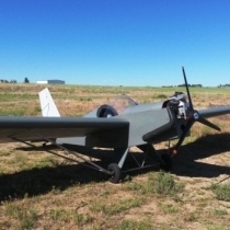
Worked on the landing gear. The spreader bars are installed. I set the axel in place and slid the wheels on again. Makes a ni e looking soap box racer. Might actually be an airplane someday.
|
|
|
|
|
|
| gyrojeffro |
|
Guest User |
Those wheels are YUGE! you should call it the bush piet  |
|
| Logged |
|
|
|
|
| cdlwingnut |
|
Ace
Posts: 416
Time Online: 3 days 22 hours 22 minutes
|
Spent a good part of they day working on the plane. The holes for the instruments were drilled and another coat of stain was applied. The floorboard was fitted around the aluminum angle the gear is bolted to and the rudder peddles were marked and holes drilled. The seat belts installed and the seat board cut so the lap belt will fit up through it. Did some work on the front turtle deck. Several other small jobs were completed
|
|
|
|
|
|
| cdlwingnut |
|
Ace
Posts: 416
Time Online: 3 days 22 hours 22 minutes
|
Kind of slow this week so more tinkering. Did some more varnishing and some work on the bell crank.
|
|
|
|
|
|
| cdlwingnut |
|
Ace
Posts: 416
Time Online: 3 days 22 hours 22 minutes
|
Installed the instruments in the panel
|
|
|
|
|
|
| gyrojeffro |
|
Guest User |
Great job cdl! I am thinking of going with a more squared off panel with all digital mgl guages on my build. |
|
| Logged |
|
|
|
|
| cdlwingnut |
|
Ace
Posts: 416
Time Online: 3 days 22 hours 22 minutes
|
That will be cool in a max gyro. I would look at dynatron or some kind of efis but i really want this plane to be a bit of a time machine into the 20s and 30s |
|
|
|
|
|
| cdlwingnut |
|
Ace
Posts: 416
Time Online: 3 days 22 hours 22 minutes
|
Fiddling with the back turtle deck
|
|
|
|
|
|
| PUFF |
|
 Ace AcePosts: 1,518
Time Online: 34 days 6 hours 18 minutes
|
what are the holes cut out in the panel behind the seat for? |
|
|
|
|
|
| cdlwingnut |
|
Ace
Posts: 416
Time Online: 3 days 22 hours 22 minutes
|
The long one is for the shoulder harness to run through. The round one is to see the gas gauge. |
|
|
|
|
|
| PUFF |
|
Ace
Posts: 1,518
Time Online: 34 days 6 hours 18 minutes
|
|
|
|
|
|
| cdlwingnut |
|
Ace
Posts: 416
Time Online: 3 days 22 hours 22 minutes
|
Nearly finished with the turtle deck.
|
|
|
|
|
|
| Keith103 |
|
 Ace AcePosts: 632
Time Online: 13 days 6 hours 31 minutes
|
Installed the instruments in the panel
I made a similar layout for my panel, cut the holes, and only now I realized that it had stated somewhere in the instructions for CHT / EGT gauge that " Do not mount this instrument closer than 12 inches from a compass." On my cut panel, the compass would come about 7 inches from the CHT/EGT gauge. Now what ? 12 inches separation on a Max panel is doable, but does it make such a big difference ? This happened partly because initially compass was not part of my panel layout, and I had made some rough mental layout on what will go where. Later when I added a compass my attention was focused on where to place it and in the bargain I forgot about this 12 inch limitation.
|
|
| Logged |
|
|
|
|
| stevejahr |
|
 Airbike plans examiner AcePosts: 200
Time Online: 4 days 11 hours 43 minutes
|
The problem is gauges which operate on magnetic mechanisms... this is why you have to calibrate the compass and have an error chart for correction. You can always check how much it swings the compass with power on and off. |
|
|
|
|
|
| Keith103 |
|
Ace
Posts: 632
Time Online: 13 days 6 hours 31 minutes
|
The problem is gauges which operate on magnetic mechanisms... this is why you have to calibrate the compass and have an error chart for correction. You can always check how much it swings the compass with power on and off.
Thanks Steve. Got it. I was concerned about the compass affecting the CHT/EGT readings. I think this gauge is more important to me as an ultralight operator than the compass. I will be mostly flying in the local area, so compass is of limited utility. |
|
| Logged |
|
|
|
|
| beragoobruce |
|
Built an Eros - now I'm flying it! AcePosts: 1,067
Time Online: 19 days 10 hours 59 minutes
|
Keith, if you need to get your compass a bit further away, you could make a mount & position it on top of the instrument coaming. This is quite often done - I'm thinking of doing this myself. Then you have space in the panel to fit a ROC indicator or maybe a fuel gauge.
Bruce |
|
|
|
|
|
| Keith103 |
|
Ace
Posts: 632
Time Online: 13 days 6 hours 31 minutes
|
Keith, if you need to get your compass a bit further away, you could make a mount & position it on top of the instrument coaming. This is quite often done - I'm thinking of doing this myself. Then you have space in the panel to fit a ROC indicator or maybe a fuel gauge.
Bruce
Bruce, thanks for the idea. I ran into some other issues on the panel, so had to remake the panel anyway. In the new layout, I moved the CHT gauge and compass to opposite ends thus eliminating the interference issue. In attached pic, some work is still to be done like routing the tach wiring towards the back. But generally this third attempt at panel cutting came out OK. My hole cutting also got progressively neater with each panel. But yes, I have also seen some other builders mounting the compass outside of panel. Thanks PS: Sorry, CDL, did not mean to hijack your thread.
|
|
| Logged |
|
|
|
|
| beragoobruce |
|
Built an Eros - now I'm flying it! AcePosts: 1,067
Time Online: 19 days 10 hours 59 minutes
|
Looks good, Keith. Just one more quick point that I learned the hard way on my panel. If you are mounting any electrical power switches (e.g. master switch, 'mag' switches) on the panel, do not tie the power leads into the same bundle as the CHT & EGT leads. I did this so I'd only have one penetration through the firewall, & my EGT's stopped working.
Turns out they are influenced by the current flowing in the switches on my panel, & the problem disappeared when I routed the power & instrument leads through firewall holes 12" apart.
Maybe this is common knowledge, but I didn't know it, & it took a while to suss the problem.
Bruce
p.s. for CDLW.nut: I agree on your instrument choice in post 138. I prefer the look of steam gauges on the Max - more traditional appearance (& less reliance on electrics). Even more so on a plane like the Piet. So hopefully this post is relevant to your thread too! |
|
|
|
|
|
|


