|
|
 stevejahr stevejahr |
| January 17, 2015, 12:15am |
|
 Airbike plans examiner Ace Posts: 200
Time Online: 4 days 11 hours 43 minutes
|
If one wanted to go crazy here... you would take a page from the Falco F8L book and build up the stringer out of laminated 1/8" spruce layers bent to the desired curve. I imagine that if one had a stair step overlap (ala scarf joing) with a solid longeron you could create a continue structural member. The Falco uses LOTS of laminated elements to create the airframe. |
|
|
|
|
|
| lake_harley |
| January 17, 2015, 12:20am |
|
Ace
Posts: 1,095
Time Online: 25 days 7 hours 43 minutes
|
I don't know why I'm even sticking my nose in on this, especially since I've seen that Brian has built "per V-Max plans" but.....isn't the load bearing strength of the forward part of the fuselage actually coming from a combination of the plywood sides along with the longerons in tension (top) and compression (bottom)? Buckling of the notched lower longeron would be resisted by the side and bottom ply. It's not like the weight of the VW engine is hanging off of cantilevered RS-10 sticks that have been notched, bent and then reinforced with the extra plywood strip.
Lynn |
|
|
|
|
|
| beragoobruce |
|
Built an Eros - now I'm flying it! AcePosts: 1,067
Time Online: 19 days 10 hours 58 minutes
|
Yes, you're quite correct Lynn. The deep plywood sides act as a shear web to take much of the engine loads.
And Brian is doing an excellent job in his build, and in carefully following the factory drawings.
But Brian himself said how he hated to cut the longerons, as would I. It just seems so silly to do it this way when you could just bend the extended longerons & cut them off when the glue has cured. This is quite common in boatbuilding, for example. That way, the integrity of the longerons is assured, & you don't have to worry about whether you mixed the glue properly, whether it's going to soften in the heat of the engine bay, what will happen as it ages & vibrates, & so on.
I'll butt out now.
Bruce |
|
|
|
|
|
| bigbrixx1 |
|
 Ace AcePosts: 822
Time Online: 20 days 16 hours
|
First My apologies for the upside down photos.......I am unable to see them. I take the photos with my Iphone. Load them with my Ipad and view thru the same devices. They show me the photos as upright!!!!!! Now as far as the saw cuts in the nose section I am sure there are more elegant solutions to this problem. It seems to me the Minimax design favors simplicity. I picked it because it's a proven design. I hesitate to vary from the plans. Beef up one area and it is possible to cause stress to rise in another and create a failure point!
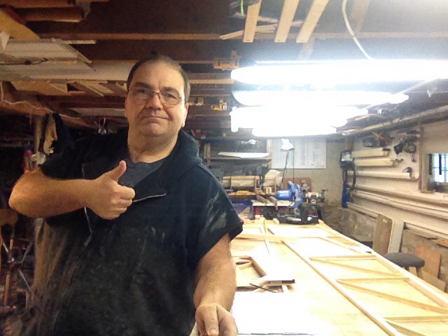
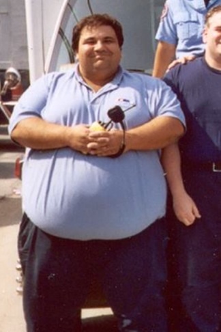
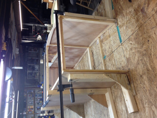
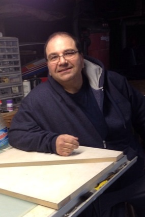
Today I was able to square up the frame sides and glue in supports in the cockpit area including rear carry thru at section 4. Using table saw it put In the 2 percent angle to front carry thru and glued that in place also. Everything is kept square via 90 degree L shaped frames as suggested by Bruce! Notice less if me! Add 1.8 pounds to loss column. And of course a selfie for the FAA guys
|
| V-max. Finished. Now in phase one flight |
|
|
|
|
|
| lake_harley |
|
Ace
Posts: 1,095
Time Online: 25 days 7 hours 43 minutes
|
I can't really recall exactly how I clamped the sides together during the same point of construction on my MiniMAX, but I don't think it was quite so well thought out or executed. Looking good.....as always. BTW.....who's the thin fellow in the picture? Did this project get taken over by a different builder?  Lynn |
|
|
|
|
|
| Ricardo |
|
 Videos in UTube: ral1951 AcePosts: 2,772
Time Online: 75 days 23 hours 15 minutes
|
...BTW.....who's the thin fellow in the picture? Did this project get taken over by a different builder? Lynn
I was going to say the same, I think you're going to beat the plane! Congratulations man..what a lesson! |
|
|
|
|
|
| Tom |
| January 17, 2015, 12:16pm |
|
Ace
Posts: 744
Time Online: 16 days 10 hours 21 minutes
|
I do think the builder is correct to stick to the plans. However I also think it is a mistake to assume that the average person building one of these plans wouldn't be better off to steam bend the wood to shape. Steam bending is very simple to do and you'd end up with a structure that was lighter and full strength without making it into a sandwich construction. There is no disadvantage to steam bending and its bone simple to do. I would recommend that the plans be modified to show a simple steam bend member here.
Tom |
|
|
|
|
|
| bigbrixx1 |
|
Ace
Posts: 822
Time Online: 20 days 16 hours
|
I was going to say the same, I think you're going to beat the plane!
Congratulations man..what a lesson!
Thanks guys......here is a photo of me about 7 years ago........I don't know how I let it happen.......as far as modifying the plans. Steaming and laminating the front end do seem like great ideas. The plane favors simplicity... Hence butt joints in plywood vs scarf joints ect.... I suspect they went this way in order to keep the skill set required low. That way guys like me can build it also The cuts are made I made..... I picked the Max due to its long and safe history. I am sticking to the plans...... I am moving forward. I will leave changes to people who have much more knowledge on that matter.
|
| V-max. Finished. Now in phase one flight |
|
|
|
|
|
| Bob Daly |
|
Ace
Posts: 888
Time Online: 45 days 22 hours 25 minutes
|
Let's do some armchair analysis of the fuselage structure and see if we can alleviate the concerns over the kerfs cut in the longerons. I'm going to say the stress is highest as a result of the engine download from a 6g pull-up so we have about a 23,000 in-lb moment at the fuselage station just ahead of the cockpit. The calc is 120lbs x 6gs x 32 inches (engine position ahead of the cockpit). We'll assume the twin 1/8" ply 20" wide sides can react the 720lbs shear load since a single 1/16" ply 6" web in the wing takes the maximum 293lb shear calculated there for a Minimax 1100R. So then the stress in the longerons just ahead of the cockpit is 23,000/10 inches(half the fuselage depth)/4 longerons = 575 lbs. This will be compression in the bottom longerons and tension in the tops. The ultimate compression for white pine is 5240 psi from ANC-18 so the longerons can take 982 lbs (5240 x .75 x .25) at the kerf cuts in compression. For tension we'll use the modulus of rupture, 9300 psi, so surely the 575 lbs tension is not a problem. And certainly the plywood skin immediately adjacent and bonded to the longerons contributes to the strength. I'll also mention that there is a notation in the Minimax Structural Analysis report that states the forward fuselage has a minimum safety factor greater than 10.
Oops, forgot the tail load! This will be in the neighborhood of 300 lbs downward at about 120" from the same fuselage station so an additional moment of 36,000 in-lbs. This is additive, so the stress in the longerons becomes 1475 lbs! So while we're still ok as far as tension is concerned, there's a discrepancy of 495 lbs on the compression side. If we fill the kerfs with epoxy we should be good as System Three says T88 has a compressive strength of 12,500 psi(!). |
|
 Logged Logged |
|
|
|
|
| texasbuzzard |
|
 airbike Buzzard AcePosts: 1,238
Time Online: 8 days 23 hours 51 minutes
|
Wow Bob I have no idea on what you said but it's sounds like you paid attention in school. If I was building a max like Brixx and cut the kerfs in the longerons, I would sleep real good.
Monte |
|
|
|
|
|
| George Sychrovsky |
|
Guest User |
This is not about if the fuselage is strong enough for flying around , this is about what happens when you come down on the nose instead the landing gear, like this https://www.youtube.com/watch?v=YOIXx5r-Y6gTake a note that was just a hard thug from not much height and speed , the rest of the plane is still all intact and the front cockpit area is disintegrated. I have collected (and later lost) many pictures of crashes looking just like this, This pilot was lucky but many other pilots got badly busted legs. thats why I modified both of my fuselages like this. http://www.n566aj.com/cgi-bin/bbs/archive.cgi?read=22358 |
|
| Logged |
|
|
|
|
| Ricardo |
|
Videos in UTube: ral1951 AcePosts: 2,772
Time Online: 75 days 23 hours 15 minutes
|
I remember George's post and did follow his advise. It makes sense and there's always room for improvement specially when a safety issue is in play. The wheight increase is nil and havind that diagonal member was also a good place to attach the throttle and fuel valves comming from each tank. |
|
|
|
|
|
| bigbrixx1 |
|
Ace
Posts: 822
Time Online: 20 days 16 hours
|
Landing gear legs built, sanded ready for final cuts
|
| V-max. Finished. Now in phase one flight |
|
|
|
|
|
| bigbrixx1 |
|
Ace
Posts: 822
Time Online: 20 days 16 hours
|
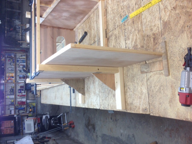
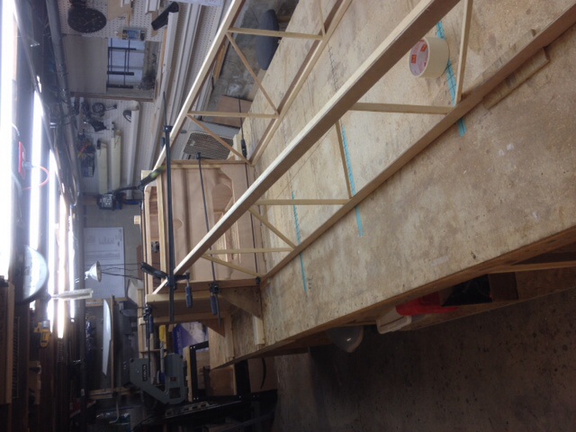
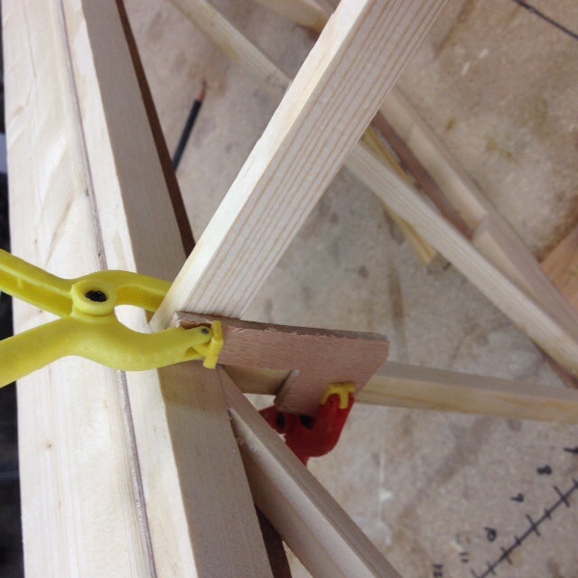
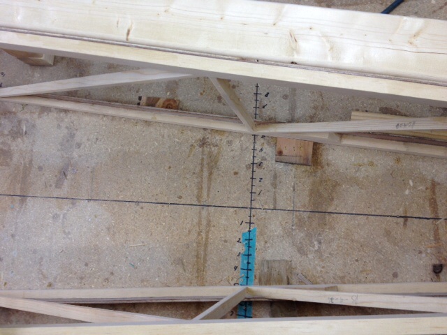
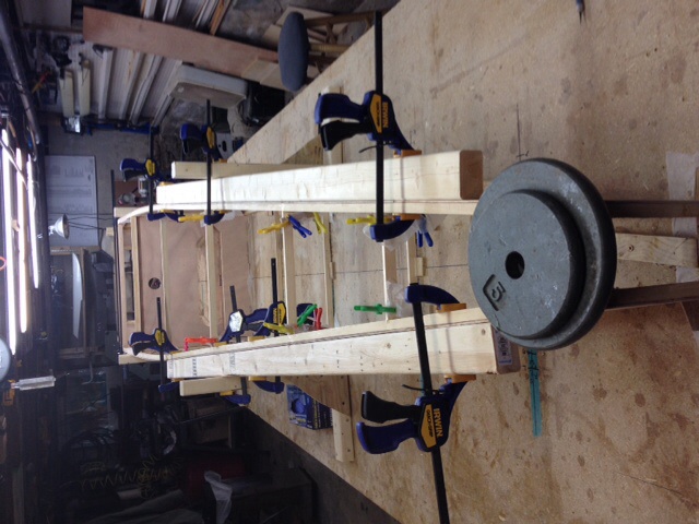
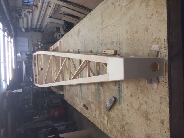
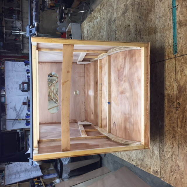
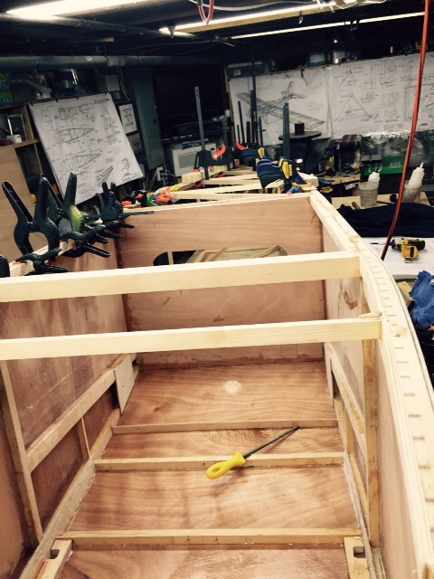
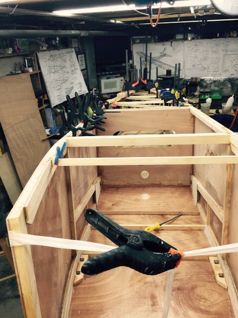
Fuse had nose pulled in. Front RS 11 fit and glued in. Tail pulled together. Cross members glued and drying. Notice braces to keep everything 90 degrees. When building R/C airplanes they were the only way I could build and not end up with bananna for a fuse. One problem I ran into was keeping the cross braces in place while glue dried. I made brackets out of left over plywood. You can see how they were used. They work great! Also notice how I drew a scale to either side of center line at each bulkhead station to ensure sides were spaced out properly!
|
| V-max. Finished. Now in phase one flight |
|
|
|
|
|
| bigbrixx1 |
|
Ace
Posts: 822
Time Online: 20 days 16 hours
|
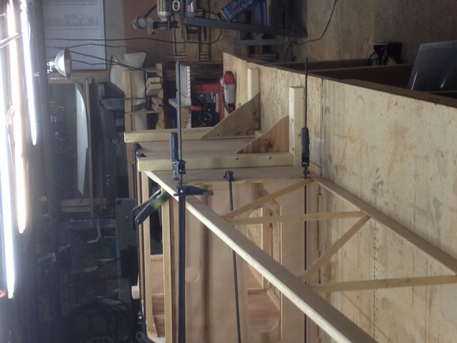
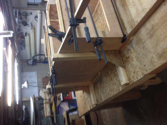
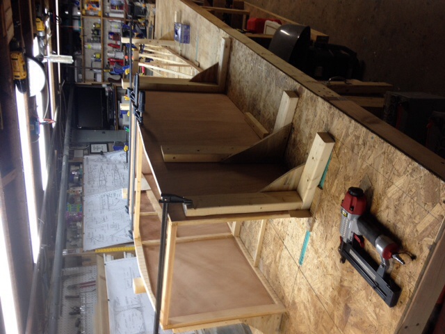
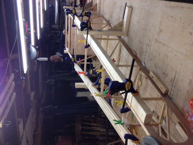
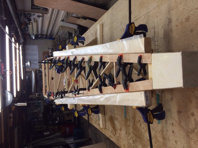
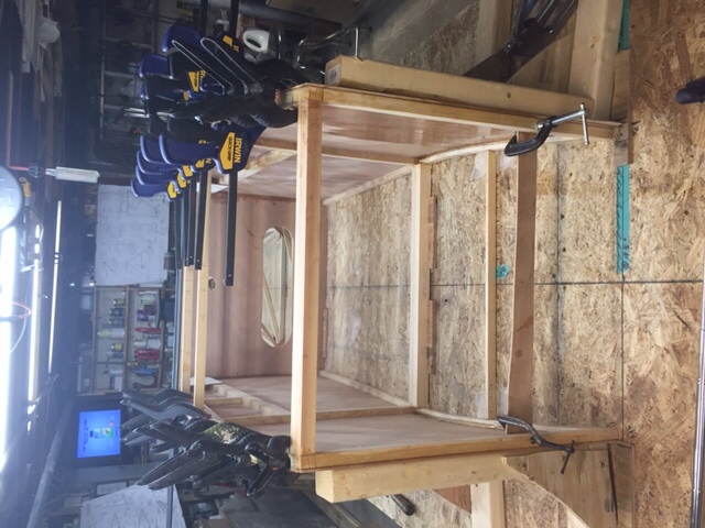
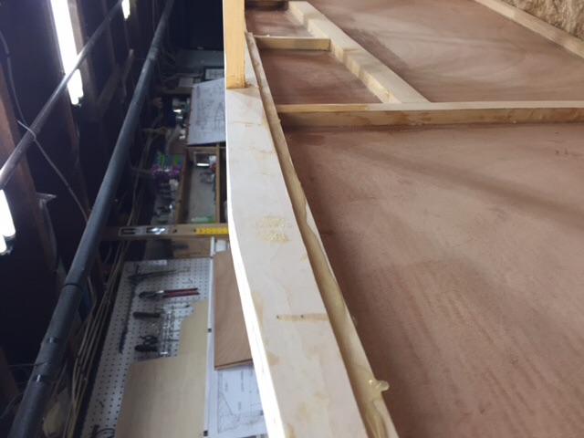
Couple more pics. Notice 2x3 used to keep sides straight from station 5 back to tail! Sides are equal and square. Picture makes them look offset. They are not! You notice I also kept the clamps on the cross braces in cabin area. I don't want them popping off when forming the nose and tail. I plan on leaving them on for three days. That's about how long the T-88 takes to cure completely in my 58 degree (on average ) workshop.
|
| V-max. Finished. Now in phase one flight |
|
|
|
|
|
| bigbrixx1 |
|
Ace
Posts: 822
Time Online: 20 days 16 hours
|
Couple more for the FAA
|
| V-max. Finished. Now in phase one flight |
|
|
|
|
|
| bigbrixx1 |
|
Ace
Posts: 822
Time Online: 20 days 16 hours
|
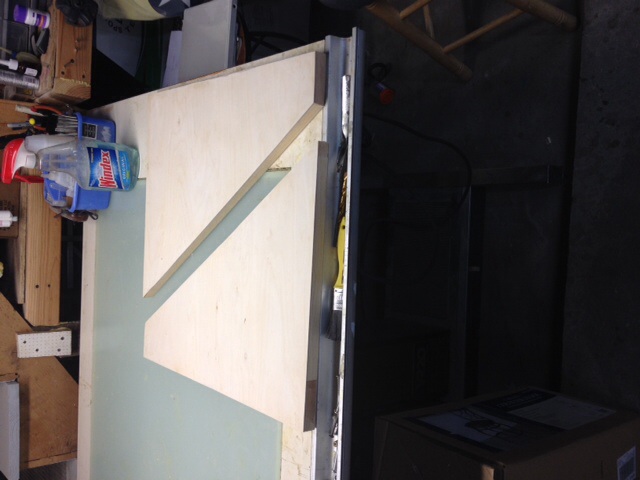
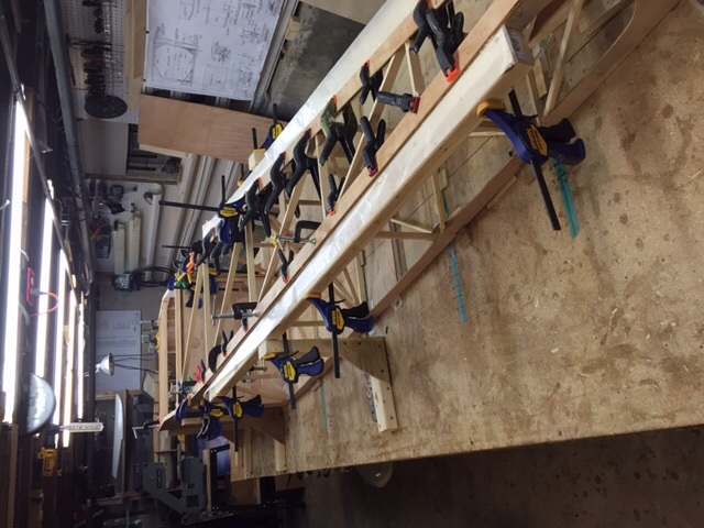
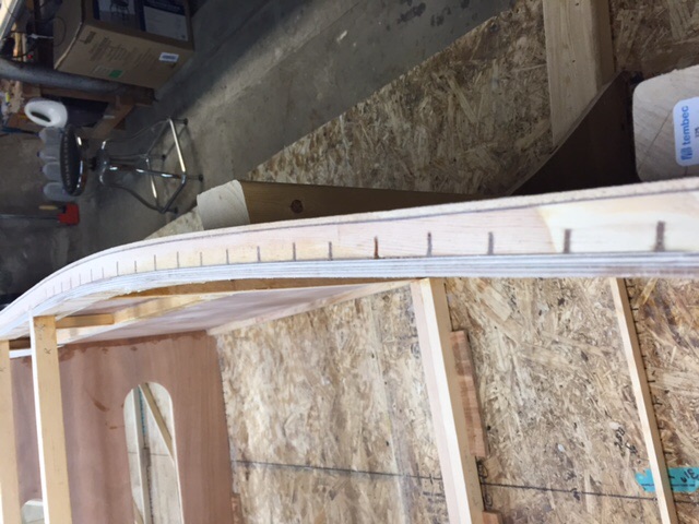
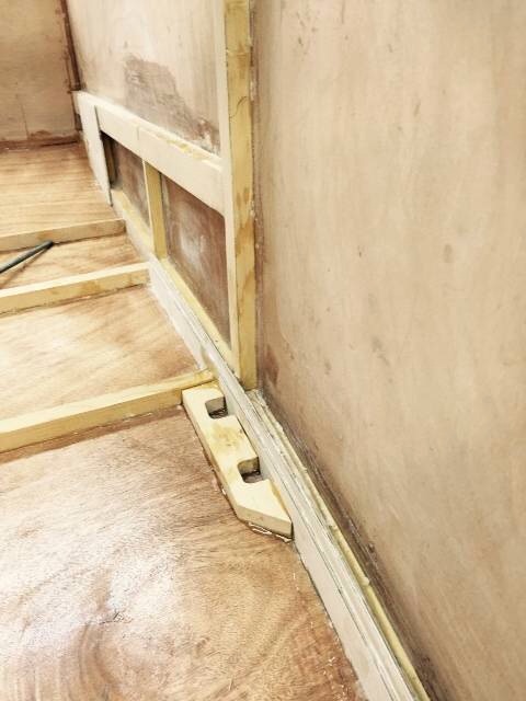
Plywood strips added to bottom rear of fuse longer owns. Nice pic here of cuts made in strips for the bend. Cuts doubled from underneath and filled with epoxy. Very straight 2 x 3 used to keep sides straight from station 5 back. Wax paper used to keep "squeeze out" epoxy from accidentally gluing 2 x 3 to airframe. Once dry, 2x3 and rear L brace removed and excess glue cleaned up! Fuse still jigged to table top! Will remain there until forward area completed and sheeted to keep everything straight!
|
| V-max. Finished. Now in phase one flight |
|
|
|
|
|
| bigbrixx1 |
|
Ace
Posts: 822
Time Online: 20 days 16 hours
|
Clamps removed. Braces removed. Excess glue cleaned up and light sanding.
|
| V-max. Finished. Now in phase one flight |
|
|
|
|
|
| bigbrixx1 |
|
Ace
Posts: 822
Time Online: 20 days 16 hours
|
Front doublers clamped and glued. All kerfs filled with epoxy |
| V-max. Finished. Now in phase one flight |
|
|
|
|
|
| bigbrixx1 |
|
Ace
Posts: 822
Time Online: 20 days 16 hours
|
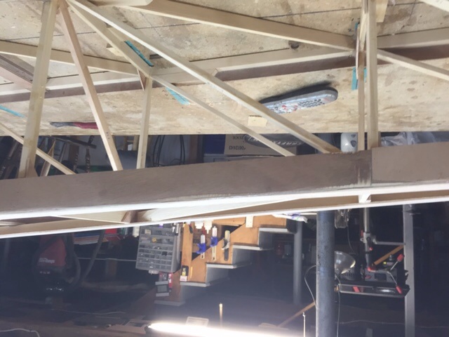
Lower longeron, forward doublers in place. Glued and clamped. Kerfs filled with epoxy. Drying! Notice scrap plywood glued across nose to keep sides from springing out when it is time to flip the whole assembly. It will be removed when top is sheeted. 1.8 pound loss since last report. 62 lbs total
|
| V-max. Finished. Now in phase one flight |
|
|
|
|
|
| bigbrixx1 |
|
Ace
Posts: 822
Time Online: 20 days 16 hours
|
What no smile....... Why no smile??????? Next time!
|
| V-max. Finished. Now in phase one flight |
|
|
|
|
|
| bigbrixx1 |
|
Ace
Posts: 822
Time Online: 20 days 16 hours
|
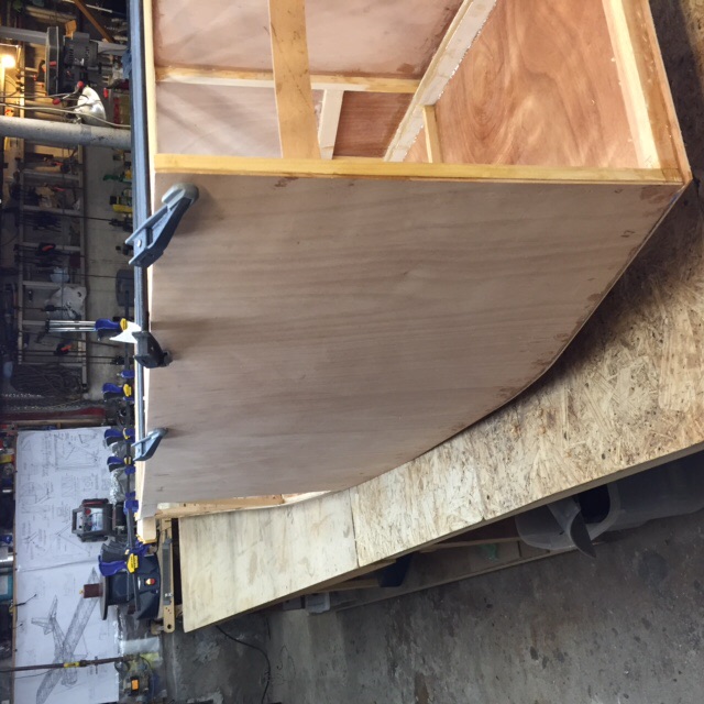
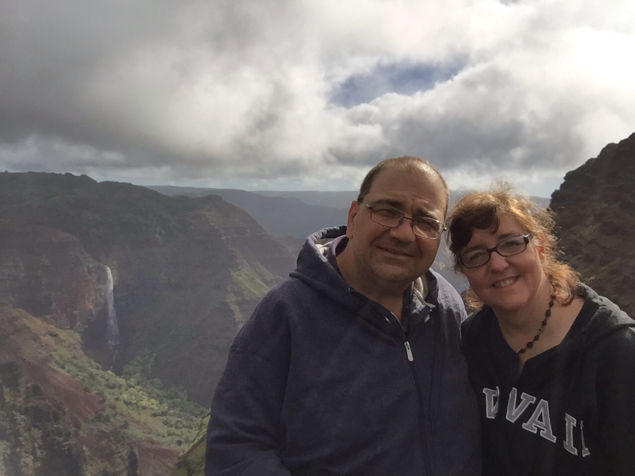
Bottom sheeted, fuse has been flipped upright, decided to double up plywood reinforcement along lower forward section, still need to clean up "squeeze out" epoxy. Fuse out of jig, upright. Clamps added just to ensure sides do not spring apart until reinforced, there will not be any updates for a couple weeks, off to Hawaii for a vacation. My vitamin D must be depleted here in the basement. A trip to Hawaii to replenish it seems excessive, but the wife claims it is necessary! Touring a bunch of the islands and have a rental car, any Minimax builders or owners out there???? Let me know, love to stop by and check it out!
|
| V-max. Finished. Now in phase one flight |
|
|
|
|
|
| bigbrixx1 |
|
Ace
Posts: 822
Time Online: 20 days 16 hours
|
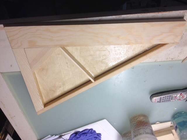
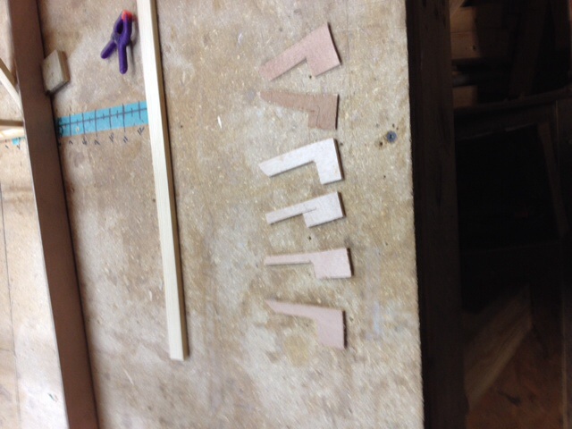
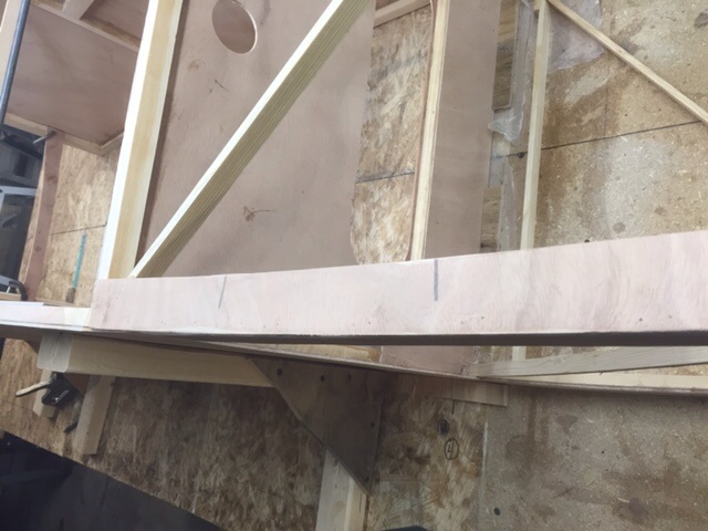
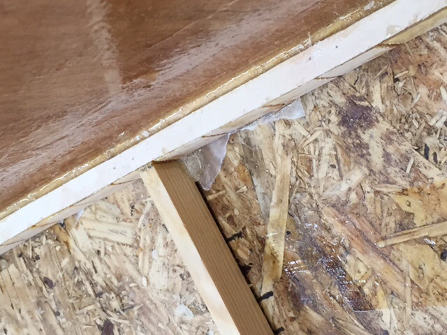
One more item...Had a problem filling in kerfs, epoxy kept flowing out and making a mess, tried tape along bottom but was messy. Finally added strips 1.5 mm plywood along base of kerfs then added side plywood reinforcement panels and flowed in epoxy. Gently heated with heat gun allowed epoxy to flow well. First photo shows plywood strips bottom view. Grams in weight gain. Some added strength.... Second photo shows finished edge. View from the top. Warm epoxy will flow to bottom of kerf. I probe with a needle to ensure there are no trapped air bubbles!
|
| V-max. Finished. Now in phase one flight |
|
|
|
|
|
| PUFF |
| January 27, 2015, 12:27pm |
|
 Ace AcePosts: 1,518
Time Online: 34 days 6 hours 18 minutes
|
|
|
|
|
|
| Tom |
|
Ace
Posts: 744
Time Online: 16 days 10 hours 21 minutes
|
You can thicken the epoxy with various fillers depending on the characteristics you want. I would download everything that looks useful from http://www.westsystem.com > How to Use > Use guides. You should be able to tailor your epoxy mix to exactly the characteristics you want. I don't work for this company or get any special treatment from them. I've just been using their products with wood since 1977. No need for problems with epoxy not staying in the joints. Tom |
|
|
|
|
|
| bigbrixx1 |
|
Ace
Posts: 822
Time Online: 20 days 16 hours
|
You can thicken the epoxy with various fillers depending on the characteristics you want. I would download everything that looks useful from http://www.westsystem.com > How to Use > Use guides. You should be able to tailor your epoxy mix to exactly the characteristics you want. I don't work for this company or get any special treatment from them. I've just been using their products with wood since 1977. No need for problems with epoxy not staying in the joints. Tom
I actually have fumed silica as a thixatropic agent. I hesitated to use it in case it weakened the epoxy in such a critical area. Great link thank you! Another photo of doubler on lower longeron. Epoxy "squeeze out" still needs to be cleaned up
|
| V-max. Finished. Now in phase one flight |
|
|
|
|
|
| alex3 |
|
Wing Man  Posts: 80
Time Online: 1 days 22 hours 51 minutes
|
Enjoy Hawaii. Big waves this time of year. Maui my favorite. Road to Hana excellent drive! |
|
|
|
|
|
| bigbrixx1 |
| February 13, 2015, 9:19pm |
|
Ace
Posts: 822
Time Online: 20 days 16 hours
|
Enjoy Hawaii. Big waves this time of year. Maui my favorite. Road to Hana excellent drive!
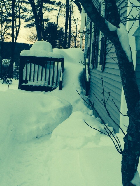
The road to Hanna was great and waves were big! Sadly we are home. Left this came home to snow! Vit-D replenished! Back to the basement
|
| V-max. Finished. Now in phase one flight |
|
|
|
|
|
| bigbrixx1 |
| February 13, 2015, 9:21pm |
|
Ace
Posts: 822
Time Online: 20 days 16 hours
|
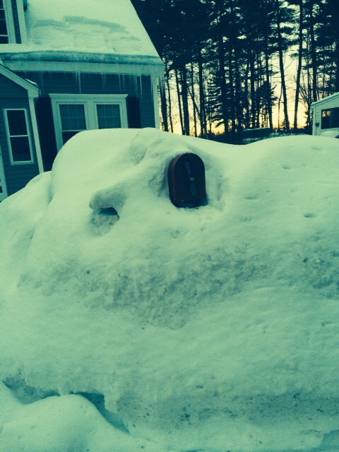
One more left this....Came home to .....hidden under that snow is an adorable airplane mailbox! Add 1.6 pounds to the weight loss. Not bad on vacation! Esp a cruise. That's our ship In background!
|
| V-max. Finished. Now in phase one flight |
|
|
|
|
|
| bigbrixx1 |
| February 13, 2015, 9:29pm |
|
Ace
Posts: 822
Time Online: 20 days 16 hours
|
Build continues. Framing on fuse cont. top forward doublers added. LG reinforcements added. Top rear longeron cap strips added. Note plywood used to keep sides straight until longeron cap strips dry completely. Cockpit RS-8 doublers added here. workshop modified so fuse can be completed. My ceiling is low so fuse on workbench too tall to complete turtle deck. Workbench extensions broken down. Sawhorses made to hold fuse
|
| V-max. Finished. Now in phase one flight |
|
|
|
|
|
|