|
|
 Reto S Reto S |
|
Ace
Posts: 320
Time Online: 13 days 19 hours 26 minutes
|
Really good plywood can be essentially a work of art in itself. We see so much horrible stuff it's hard to believe how perfect the really good stuff can be. The top quality stuff is much stronger than the mediocre stuff too. It never really costs that much more.
Tom
Hi Tom Couldn't agree more. Cheers Reto |
|
|
|
|
|
| Reto S |
|
Ace
Posts: 320
Time Online: 13 days 19 hours 26 minutes
|
Great job on the cowlings, Reto. Especially considering all the relocating work you had to do for a non standard engine. I'm looking at how much I'll have to do on the cowlings to fit a different engine, and it's a lot of work.
Have you looked into which propellor you will use for the Hirth?
Bruce
Hi Bruce Yup, happy that at least the cowling is done... Just a thought... there will be little margin to alter your trust line if your 503 engine support plate is installed (and you would like to use the original cowling). You might want to get all the technical drawings of the engines you consider and see which engine/gearbox combination will fit (the 503 is very compact compared to other engines). For the Hirth I had to extend the nose section because it needed to be installed at a min distance from the firewall for cooling fan air intake). About a year ago I looked into the prop issue. Got so many different opinions regarding fixed pitch prop size/pitch that I finally went for a GSC-2 blade-wood prop with adjustable pitch. It's beautifully done and has leading edge protection. The CNC machined hub is excellent. http://www.ultralightprops.com/Cheers Reto |
|
|
|
|
|
| beragoobruce |
|
Built an Eros - now I'm flying it! AcePosts: 1,066
Time Online: 19 days 10 hours 52 minutes
|
They look nice props. From Peter's experience it seems you need a fair bit of blade area to absorb all those lovely Hirth horsepower. Though I don't suppose you have to use all of them if you choose not to. I'll be very interested to hear how your system works later on. My platform is already built to accept a 503, but is too high for the belt reduction drive MZ 201 I'm considering at the moment. The belt pulley centres are about 50mm further apart than the gear centres. I have temporarily 'installed' the upper cowling, angled up to suit the MZ 201 thrust line. It doesn't look right, & I will have trouble extending the lower cowl by 2" to suit the higher prop centre. So I am currently on the drawing board deciding the best way to lower the engine mount. It's fun this aircraft building, isn't it?  I am not concerned by the small difference in the thrust line as regards it's effect on flying. I very much doubt it will be noticeable. But the appearance is surprisingly a lot worse with the upper cowl tilted up. D'Oh! Bruce |
|
|
|
|
|
| Reto S |
|
Ace
Posts: 320
Time Online: 13 days 19 hours 26 minutes
|
They look nice props. From Peter's experience it seems you need a fair bit of blade area to absorb all those lovely Hirth horsepower. Though I don't suppose you have to use all of them if you choose not to. I'll be very interested to hear how your system works later on. My platform is already built to accept a 503, but is too high for the belt reduction drive MZ 201 I'm considering at the moment. The belt pulley centres are about 50mm further apart than the gear centres. I have temporarily 'installed' the upper cowling, angled up to suit the MZ 201 thrust line. It doesn't look right, & I will have trouble extending the lower cowl by 2" to suit the higher prop centre. So I am currently on the drawing board deciding the best way to lower the engine mount. It's fun this aircraft building, isn't it? I am not concerned by the small difference in the thrust line as regards it's effect on flying. I very much doubt it will be noticeable. But the appearance is surprisingly a lot worse with the upper cowl tilted up. D'Oh! Bruce
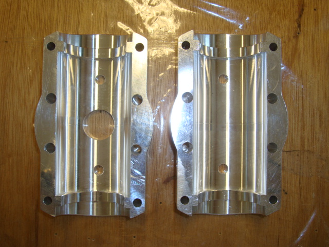
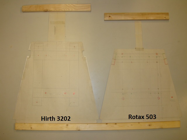
Hi Bruce I just came across my original Hirth & Rotax engine plate templates. Quite a difference... Did you consider installation of gearbox and/or engine upside down? Might help. The second pic is the GSC propeller hub. Cheers Reto
|
|
 |
|
|
|
|
|
|
| Reto S |
|
Ace
Posts: 320
Time Online: 13 days 19 hours 26 minutes
|
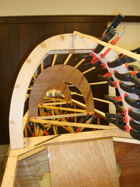
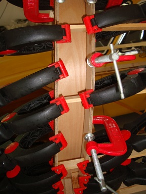
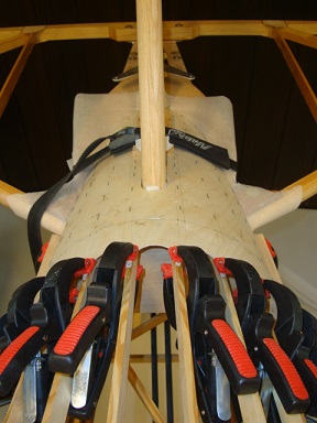
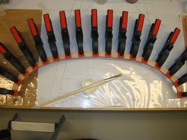
The clamp man did it again...
|
|
|
|
|
|
| Reto S |
|
Ace
Posts: 320
Time Online: 13 days 19 hours 26 minutes
|
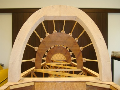
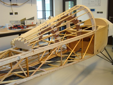
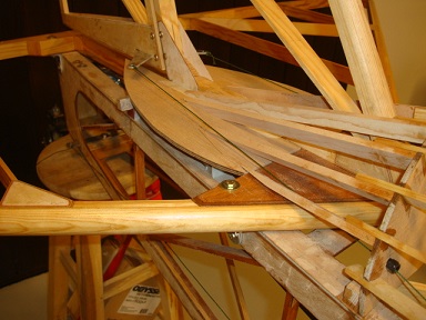
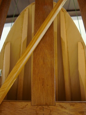
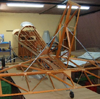
Rear turtle deck done..
Stringer curvature progressively less towards the top..
|
|
|
|
|
|
| PUFF |
|
 Ace AcePosts: 1,518
Time Online: 34 days 6 hours 18 minutes
|
Look out Huns! The fabrics starting to go on! |
|
|
|
|
|
| Reto S |
|
Ace
Posts: 320
Time Online: 13 days 19 hours 26 minutes
|
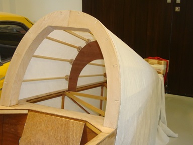
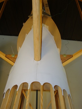
Look out Huns! The fabrics starting to go on!
hahaha, that might still take a while, just put a cloth over it to check the shape... Cheers, Reto |
|
|
|
|
|
| viktorvonragaman |
|
 Wing Man  Posts: 74
Time Online: 1 days 7 hours 55 minutes
|
your work is so nice .. that last pic looks like a piece of artwork. very clean!! |
| "There is violence that exists between men on the ground....there is respect among the clouds."
unknown pilot 1917 |
|
|
|
|
|
| Reto S |
|
Ace
Posts: 320
Time Online: 13 days 19 hours 26 minutes
|
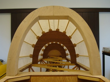
your work is so nice .. that last pic looks like a piece of artwork. very clean!!
Thank you for your kind words, you should have seen the mess though during scratching all the glue off and the wood in shape with a cutter blade... Cheers, Reto |
|
|
|
|
|
| aeronut |
|
 blue sky and tail winds to everyone AcePosts: 1,560
Time Online: 28 days 22 hours 31 minutes
|
That is great looking work. Hope you are able to continue your fantastic build. Thanks for posting. |
| never surrender; never give-up |
|
|
|
|
|
| Reto S |
|
Ace
Posts: 320
Time Online: 13 days 19 hours 26 minutes
|
That is great looking work. Hope you are able to continue your fantastic build. Thanks for posting.
Hi aeronut Thank you. You said it: "Never surrender, never give up..." Cheers, Reto Q.E.D. "quod erat demonstrandum" |
|
|
|
|
|
| Reto S |
|
Ace
Posts: 320
Time Online: 13 days 19 hours 26 minutes
|
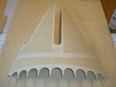
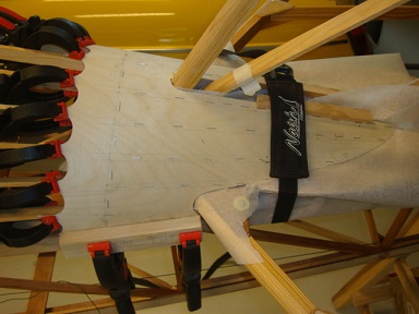
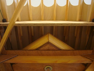
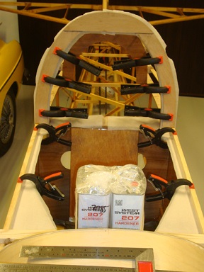
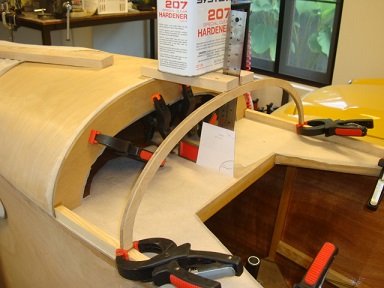
Epoxy rear fairing wouldn't fit nicely.
Went for rear ply fairing with stringer extension, similar to Bruce's layout...
|
|
|
|
|
|
| Reto S |
|
Ace
Posts: 320
Time Online: 13 days 19 hours 26 minutes
|
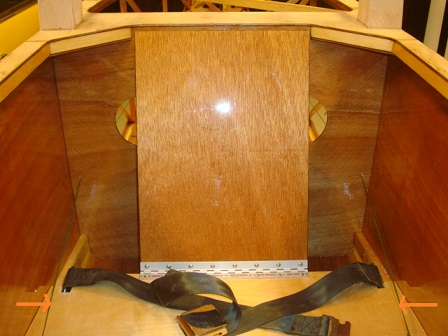
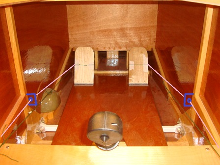
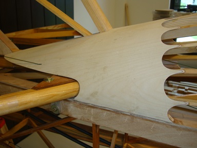
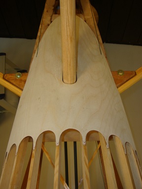
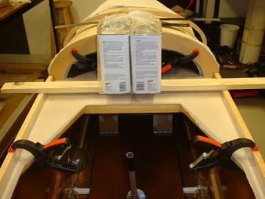
Just realized when I wanted to glue the rear ply fairing in place, that I better hook up the rudder/tail wheel controls beforehand. This to ensure no conflict exists with extended stringers. All is fine at the back.
But...
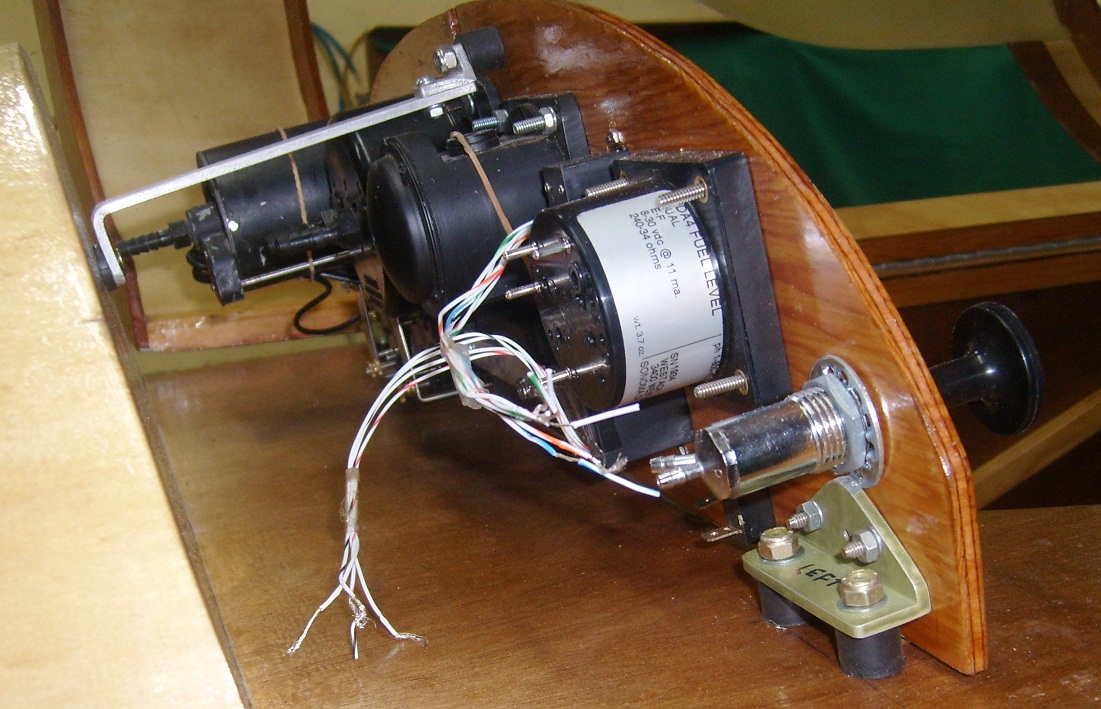
Inside the cockpit the (original) cable routing is quite a bit off the side walls (see picture 1). I wonder if a second cable fairlead could be installed to re-route the cables closer to the side walls ( see picture 2)?
|
|
|
|
|
|
| Tom |
|
Ace
Posts: 744
Time Online: 16 days 10 hours 21 minutes
|
That rear fairing is really beautifully done.
Tom |
|
|
|
|
|
| Reto S |
|
Ace
Posts: 320
Time Online: 13 days 19 hours 26 minutes
|
I have looked at this same (issue) with mine and was thinking about trying to male some sort of an extension out from the rudder pedals for the cables to hook to in an effort to solve for the problem. Not sure that it's the best solution though. It would put the cables right next to the side wall all the way from the pedals back to the bulkhead behind the seat without the need for any angle change hardware. Might make for a more comfortable feel for your feet on the rudder pedals as well. As it is, your foot position is blocked from any further outward position as it's limited by the cable being mounted right there. It might not seem like a big deal but being able to have that little bit extra foot movement could be a considerable difference in comfort level.
Or I guess there are also options of increasing the width of the floor board and mounting the pedals at the furthest outside position OR having pedals that are shaped so as to have a big outside (bow) to them so as the cable attaching to them will again be as far to the outside as possible. It's probably simplest to mount something like Reto shows in his drawing but I see my ideas as possibly making the foot area seem more spacey (feeling). Don't think any of the ideas would require that much extra work.
Especially for a new build. Nor do I think they would be changes that effect structural integrity in any way , shape or form.
Tom, thank you for your thoughts. Did consider similar options. The outwards extension of the pedal hooking point might produce torsion stress on the pedals though. The first priority for me is to route the cable in "safer" way, second more feet/leg room. Bruce has an interesting solution routing the cables under the seat. Will sleep over it a few nights... Cheers Reto |
|
|
|
|
|
| Reto S |
|
Ace
Posts: 320
Time Online: 13 days 19 hours 26 minutes
|
Great work on the rear fairing, Reto. It's a bit fiddly, but satisfying to get it right, isn't it?
.
As to your ideas on re-routing the rudder cables, I too didn't like the idea of a control cable sharing my seat. so I ran the cables under the seat, through an extra fairlead in the forward seat bulkhead, and then through some aluminium tube to stop them fouling the seat belt. See pics below from my 'Pushrod Controls' thread.
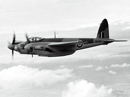
Thank you Bruce for the pictures. Yup, it's quite satisfying to get the rear fairing done nicely... I like the under seat option, because it doesn't feel right having vital control cables running 3cm next to the pilot. Tom had some ideas regarding more leg room. On an other note: Just saw a documentary of the WWII UK Mosquito bomber, it was mainly build in (birch) ply too... Impressive. Cheers Reto
|
|
|
|
|
|
| Reto S |
|
Ace
Posts: 320
Time Online: 13 days 19 hours 26 minutes
|
That rear fairing is really beautifully done.
Tom
Tom, tomorrow I shall glue the rear fairing ply on. With your kind words it will be done in a blink of an eye... Cheers Reto |
|
|
|
|
|
| Reto S |
|
Ace
Posts: 320
Time Online: 13 days 19 hours 26 minutes
|
all went well... and Bruce, yes it was a bit of a fiddle...
|
|
|
|
|
|
| beragoobruce |
|
Built an Eros - now I'm flying it! AcePosts: 1,066
Time Online: 19 days 10 hours 52 minutes
|
Looks great, Reto - good on yer.
Bruce |
|
|
|
|
|
| Reto S |
|
Ace
Posts: 320
Time Online: 13 days 19 hours 26 minutes
|
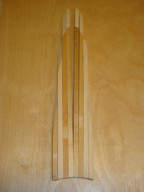
Slim instrument panel (cover) border, laminated with birch ply.
Started with Cockpit glueing...
|
|
|
|
|
|
| Reto S |
|
Ace
Posts: 320
Time Online: 13 days 19 hours 26 minutes
|
obviously baby steps...
Gents
Instrument panel:
I will install ALT/VSI/ASI/BALL/RPM/EGT/CHT/FUEL.
Is it advisable to rubber mount the entire instrument panel (vibs)?
Thank you for inputs.
Reto
|
|
|
|
|
|
| Ricardo |
|
 Videos in UTube: ral1951 AcePosts: 2,772
Time Online: 75 days 23 hours 15 minutes
|
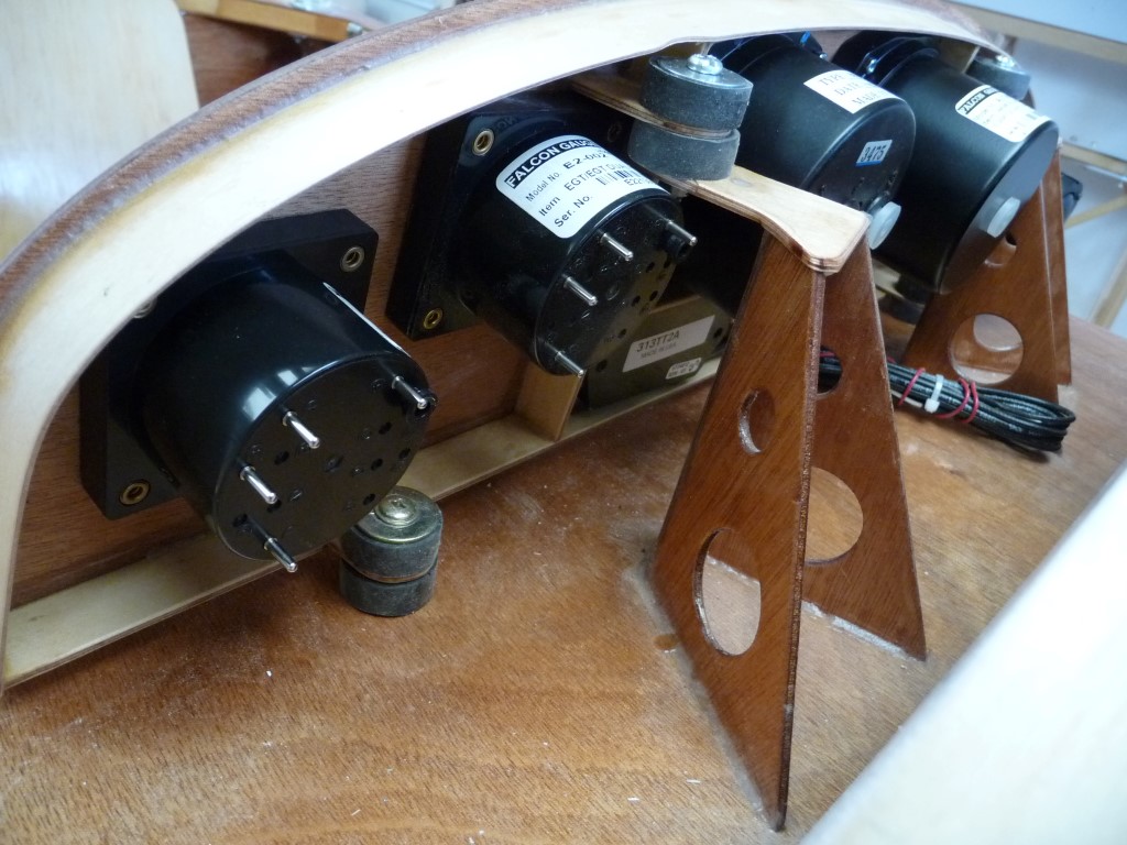
Mine is suspended by rubber supports one on each side an another in the upper middle.
The rubber pieces had inserted bolts at each end, I think they are Piper brand or else, bought them at an air show.
|
|
|
|
|
|
| Reto S |
|
Ace
Posts: 320
Time Online: 13 days 19 hours 26 minutes
|
Mine is suspended by rubber supports one on each side an another in the upper middle.
The rubber pieces had inserted bolts at each end, I think they are Piper brand or else, bought them at an air show.
Hi Ricardo/gents Thank you for the great picture. Very nicely done... I might consider to fabricate it from alu. Are there any static charge or electrical interference issues if it's made from alu? Thanks Reto |
|
|
|
|
|
| beragoobruce |
|
Built an Eros - now I'm flying it! AcePosts: 1,066
Time Online: 19 days 10 hours 52 minutes
|
|
|
|
|
|
| Reto S |
|
Ace
Posts: 320
Time Online: 13 days 19 hours 26 minutes
|
|
|
|
|
|
| Reto S |
|
Ace
Posts: 320
Time Online: 13 days 19 hours 26 minutes
|
Gents
I might consider to fabricate the instrument panel from alu.
Are there any static charge or instrument interference issues if it's made from alu?
Thanks
Reto |
|
|
|
|
|
| Harless Greear |
|
 Ace AcePosts: 884
Time Online: 35 days 14 hours 19 minutes
|
Most all GA aircraft have aluminum panels........... |
| HARLESS in Va. |
|
|
|
|
|
| Reto S |
|
Ace
Posts: 320
Time Online: 13 days 19 hours 26 minutes
|
Most all GA aircraft have aluminum panels...........
Tnx, do they ground the panel...? |
|
|
|
|
|
| Harless Greear |
|
Ace
Posts: 884
Time Online: 35 days 14 hours 19 minutes
|
I'm sure that it's grounded since it's attached to the structure that makes up the rest of the plane.. It may have an electrical ground wire for the individual instruments.. Don't know for sure.. |
| HARLESS in Va. |
|
|
|
|
|
|


 Logged