|
|
 Keith103 Keith103 |
|
 Ace Ace Posts: 632
Time Online: 13 days 6 hours 31 minutes
|
Buzz73, thanks for your feedback.
My build is a long ways from completion. I am fully aware of the huge amount of work that still needs to be done.
If I can complete it and fly it by fall next year, ( Sep - Oct 2019 ) I will consider that a great feat for me. |
|
 Logged Logged |
|
|
|
|
| Keith103 |
| February 10, 2018, 11:37pm |
|
Ace
Posts: 632
Time Online: 13 days 6 hours 31 minutes
|
Hi All, I am looking for some help with anchor nuts.
My empennage was built by the previous builder possibly almost 20 years ago. Now that I am done with building the wings, I am trying to put together the empennage. Almost all the work was done except a little work left where the horizontal stabilizer meets the elevator. I needed to make 3 steel hinges for that section, and also glue RS-2 strips to fill the gaps between the h.stabilizer and the elevator, to prevent air leakage in that section. I have completed that work too. So I proceeded to attach everything and set up the tail unit.
I just noticed that the two anchor nuts installed on the bottom rib of of the vertical stab to seat/receive the 2 bolts coming up from the horizontal stabilizer, seem to be different from the anchor nuts I had purchased from AC Spruce. They look smaller and also there is no nylon insert which I see in the newer nut. It is possible that the older nuts installed by the previous builder are to specs, but I just need to be sure.
I have attached a picture of the existing anchor nut with a new anchor nut purchased recently. Any thoughts on whether the existing nuts will do the job. It is easy to replace one nut, but the other nut is hard to reach so changing that will be an issue.
Thanks for any advise.
|
|
 |
|
|
| Logged |
|
|
|
|
| flydog |
| February 11, 2018, 1:33am |
|
Ace
Posts: 547
Time Online: 50 days 41 minutes
|
They are available in a self locking,and non-locking. You just have one of each kind. |
|
|
|
|
|
| George Sychrovsky |
| February 11, 2018, 2:11am |
|
Guest User |
They are both self locking , just one is all metal and the other with plastic insert .
What you have there is the anchor nuts supplied with kits , if used as per plans they will sink into the wood very easily and cause problems, A fix has been created to back them up with washers, the new one you bought is a lot better but I still wouldn't use it without backing.
|
|
| Logged |
|
|
|
|
| Keith103 |
| February 11, 2018, 2:54am |
|
Ace
Posts: 632
Time Online: 13 days 6 hours 31 minutes
|
Thanks George. That is the exact information I was looking for. I too had a suspicion that the previous builder must have used the correct spec anchor nut because he built from a kit purchased from Team. Also he must have read the plans which state the anchor nuts must be installed prior to gluing up the vertical stabilizer because one of the anchor nuts ( the front one ) cannot easily be removed or installed after the stabilizer is glued up.
About your other point that these sink into the wood, I will keep a watch on that during final assembly. Most likely I will replace the rear one (which is accessible), right away, and hope the front anchor nut from old stock holds.
Thanks again. |
|
| Logged |
|
|
|
|
| flydog |
| February 11, 2018, 2:49pm |
|
Ace
Posts: 547
Time Online: 50 days 41 minutes
|
Well, I did not know the all metal one is self locking. I had ordered the nylon insert self locking type for my build as there was no mention of the all metal one being self locking in the Aircraft Spruce description. |
|
|
|
|
|
| George Sychrovsky |
| February 11, 2018, 4:14pm |
|
Guest User |
|
| Logged |
|
|
|
|
| George Sychrovsky |
| February 11, 2018, 9:20pm |
|
Guest User |
Thanks George. That is the exact information I was looking for. I too had a suspicion that the previous builder must have used the correct spec anchor nut because he built from a kit purchased from Team. Also he must have read the plans which state the anchor nuts must be installed prior to gluing up the vertical stabilizer because one of the anchor nuts ( the front one ) cannot easily be removed or installed after the stabilizer is glued up.
About your other point that these sink into the wood, I will keep a watch on that during final assembly. Most likely I will replace the rear one (which is accessible), right away, and hope the front anchor nut from old stock holds.
Thanks again.
Depending how you define "correct spec anchor nut", the K 1000 type he used was shipped in the kits at the time he built, and I got them in mine, but the plans drawings actually show the bigger better AN366F type - the ones you bought. |
|
| Logged |
|
|
|
|
| Keith103 |
| February 12, 2018, 3:26am |
|
Ace
Posts: 632
Time Online: 13 days 6 hours 31 minutes
|
Quoted from 71
Depending how you define "correct spec anchor nut", the K 1000 type he used was shipped in the kits at the time he built, and I got them in mine, but the plans drawings actually show the bigger better AN366F type - the ones you bought.
George, I would prefer to have changed both of those nuts that came with the kit to new nuts that I have in my parts bin. The front nut is harder to change with only 1/2 in clearance above the screws . Even a small angled screw driver that I have needs 3/4 inch space to engage the screw. So I am leaving the front nut as is, bolstered by your confirmation that it is indeed self locking. My main concern was that those 2 nuts on the vert stab could come loose and the vert stab would fall off and I would be left flying a 2 axis plane ( lol ). Luckily for me, the remaining 4 of those anchor nuts in the kit, could not be traced, so while building the wings I had to order a total of 6 anchor nuts from Ac spruce. I installed 4 of them on the wing tip ribs, and I was not sure where the other two went. Only yesterday as I was putting together the empennage I figured those 2 belonged here. Flydog, thanks for your reply. The fact that you took time to answer my question is much appreciated. ========== I explored Google for some more info on metal lock nuts, and saw this page on AC 43.13 1B . Most builders must have already seen it; posting it only for general information. Thanks
|
|
 |
|
|
| Logged |
|
|
|
|
| George Sychrovsky |
| February 13, 2018, 5:13pm |
|
Guest User |
The front nut is harder to change with only 1/2 in clearance above the screws . Even a small angled screw driver that I have needs 3/4 inch space to engage the screw.
It can be done, I did the fix on mine after it sunk . I deepened the screw slots with dremmel cut off wheel the get better grip on them, ones I got them started straight holding them with needle nose pliers I used a small screwdriver bent the right way half turn at a time to drive them the rest of the way. One does not limit his job capabilities to the tools available from the shelf in the store , you make your own when needed |
|
| Logged |
|
|
|
|
| Keith103 |
| February 14, 2018, 10:37pm |
|
Ace
Posts: 632
Time Online: 13 days 6 hours 31 minutes
|
Quoted from 71
It can be done, I did the fix on mine after it sunk . I deepened the screw slots with dremmel cut off wheel the get better grip on them, ones I got them started straight holding them with needle nose pliers I used a small screwdriver bent the right way half turn at a time to drive them the rest of the way.
George, thanks. Sharing these small details is always helpful. |
|
| Logged |
|
|
|
|
| Keith103 |
| February 28, 2018, 1:37am |
|
Ace
Posts: 632
Time Online: 13 days 6 hours 31 minutes
|
Hi all, I have a question on seating position. The plans show the top of the seat-back is slightly displaced ahead of Station 4 by at least about 3 inches. I cant figure out how it can stay at that angle if no additional support is built at that location. Actually I like the seat-back angle shown in the plans, it suits me, but cant figure out how to make it stay at that angle. I hope the attached diagram will clarify what I am trying to say. Thanks for any suggestions.
|
|
| Logged |
|
|
|
|
| aeronut |
| February 28, 2018, 12:50pm |
|
 blue sky and tail winds to everyone AcePosts: 1,560
Time Online: 28 days 22 hours 31 minutes
|
If you look at the top view of the comm-pleated cockpit it will help to see that the rear portion is actually ahead of station#4 and the seat back top actually rests again-est the rear portion of the cockpit structure. If you have the isometric cut away view it might help to look at that. I hope this is helpful. |
| never surrender; never give-up |
|
|
|
|
|
| Keith103 |
| February 28, 2018, 5:00pm |
|
Ace
Posts: 632
Time Online: 13 days 6 hours 31 minutes
|
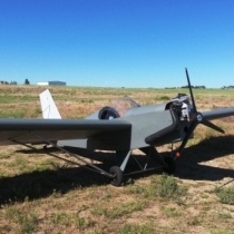
Aeronut, Thanks for responding. I am attaching some pictures to show how it is now. The top of the seat back is flush with station 4. The blue line shows the approximate location of top of seat back per plans. The present recline is angled too much backwards, and from there I find it a bit of a stretch to reach the control stick. I can move the seat bottom a couple inches back, to reduce the recline, but I want to make sure I am not missing something while reading the plans.
|
|
| Logged |
|
|
|
|
| lake_harley |
| February 28, 2018, 5:25pm |
|
Ace
Posts: 1,097
Time Online: 25 days 7 hours 59 minutes
|
Looking at the drawing you posted I understand what you're asking, but I built mine according to the other views on pages 3 and 4. The additional support shown in the other drawings show the 2nd horizontal crossmember 4" behind station 4, not 4" in front. I'm going by 1100 plans, pages 3 and 4. I wonder if the drawing you posted may have not been updated from some early plans where the seatback was larger and seved as a "bulkhead", rather than there being a separate bulkhead at station 4. I do see though what appears to be a discrepancy in the plans.
I have a bad right shoulder that limits my forward reach, so I had trouble reaching the control stick too. I put in a control stick that had a slight "S" bend in it, to position the top of the stick closer to me. The stick that I used came out of a damaged MiniMAX that I bought and parted out, so apparently we're not the only ones that have and/or had trouble with reaching the control stick.
Lynn |
|
|
|
|
|
| aeronut |
| February 28, 2018, 5:48pm |
|
blue sky and tail winds to everyone AcePosts: 1,560
Time Online: 28 days 22 hours 31 minutes
|
That is just about what mine looks like but the angle of the seat back looks to be more reclined than mine.Your airplane has a fixed turtle deck while mine does not. I suppose you could make up the difference with a back cushion. Have the seat belt attach bolt holes been drilled yet. I think that they will determine how far back you can push the bottom of the seat. From image 1005 it looks like the bottom of the seat can be moved back about 2", which would steepen up the seat back. My seat back is attached with a piece of strip hinge. What are those attachment screws on the seat bottom going into? |
| never surrender; never give-up |
|
|
|
|
|
| aeronut |
| February 28, 2018, 6:34pm |
|
blue sky and tail winds to everyone AcePosts: 1,560
Time Online: 28 days 22 hours 31 minutes
|
Keith I am working strictly from memory. I am in Florida right now and my Max is in Maine along with the plans. So I would deffer to lake harley in this matter. My airplane started construction 28 years ago and has been flying for 18 years. The plans I have were drawn up as TEAM transitioned from their original format to the format that they use today. I had some problems with the plans at that time because of omissions and such. I was trying to be helpful but I am glade that lake harley has chimed in . |
| never surrender; never give-up |
|
|
|
|
|
| Keith103 |
| February 28, 2018, 9:51pm |
|
Ace
Posts: 632
Time Online: 13 days 6 hours 31 minutes
|
....The additional support shown in the other drawings show the 2nd horizontal crossmember 4" behind station 4, not 4" in front. I'm going by 1100 plans, pages 3 and 4.....
I wonder if the drawing you posted may have not been updated from some early plans where the seatback was larger and seved as a "bulkhead", rather than there being a separate bulkhead at station 4. I do see though what appears to be a discrepancy in the plans.
Lynn
Lynn, I totally agree with your observations. Mine is an old paper plan , but it is same as a recent 1100 plan on pages 3 and 4. The seat back is only 12 inches wide so it slides all the way back to station 4. And the cross member that you are mentioning is 4 inches behind station # 4, and not ahead of it. Over 1000 of these planes have been built, so the first thought that hits me when I see something not making sense, is that I am missing something. My seat back angle is now reclined about 22 degrees back from vertical. Is that the accepted number ? (Edit - Sorry that is 29 degrees back from the vertical. The difference of 7 degrees is because the front of the seat is already raised from horizontal by 7 degrees.) Like in your build, a control stick with the top recessed back by about 3 inches is also an option I am considering. Thanks for your response, Lynn. Aeronut , thanks for sharing your thoughts. Much appreciated. |
|
| Logged |
|
|
|
|
| Keith103 |
| February 28, 2018, 10:34pm |
|
Ace
Posts: 632
Time Online: 13 days 6 hours 31 minutes
|
Here are the seating angles:
|
|
| Logged |
|
|
|
|
| lake_harley |
|
Ace
Posts: 1,097
Time Online: 25 days 7 hours 59 minutes
|
I'm no where near my plane either to take a look at it for reference, and perhaps I built mine wrong...it's certainly possible. I will throw out one suggestion; double check that your vertical seat support members are at the proper locations and that the seat bottom is positioned correctly per the dimensions on page #1, including the detail "D" drawing in the upper right of page #1, and the drawing you had in your post number 101. From the photos you posted the locations appear to be correct though. Also, how much overhang "lip" does your seat bottom have forward of the seat support bulkhead?
Just out of curiosity I looked at my set of "original" MiniMAX plans that use the seat back as a bulkhead. The seat support structure is totally different from the "newer" 1100 plans, so I am less inclined to thing there's any mixing of old and new plans on the current ones. Interestingly though, the seat position in the "old" plans appears to be about 4" bit farther forward in general, compared to current plans. I'd suppose that was for W&B reasons since the "original" MiniMAX was probably intended for a relatively light 277 Rotax. That would explain why my 277 Rotax/1100 ended up on the borderline of tail heavy until I moved my engine forward and use a 1" thick piece of foam as a backrest to move my weight forward.
I might be at my plane in a few days and if I remember I'll take an angle measurement of the angle between the seat bottom and the seat back for your comparison.
Lynn |
|
|
|
|
|
| George Sychrovsky |
|
Guest User |
It is a mistake in the drawing, contained in minimax plans versions but if you download 1700R HiMax plans dr #4, it will show the seat bottom and seat back both further to the rear with the front edge of the seat right over the vertical cross seat support plywood in the correct position which will retain the similar seat back angle as the original minimax where the seat back was a solid bulkhead. |
|
| Logged |
|
|
|
|
| George Sychrovsky |
|
Guest User |
Whoa, I used my new sniping tool to snipe the pic from PDF
|
|
| Logged |
|
|
|
|
| lake_harley |
|
Ace
Posts: 1,097
Time Online: 25 days 7 hours 59 minutes
|
George....I'll say thank you for posting that drawing and the seat bottom location info. With that, I believe my seat is positioned incorrectly. I believe on my plane the seat bottom overhangs the seat support bulkhead by 1" or so, but I'll certainly take a look when I get to the hangar.
Lynn |
|
|
|
|
|
| PUFF |
|
 Ace AcePosts: 1,518
Time Online: 34 days 6 hours 18 minutes
|
No matter what you do, make sure that your weight and balance come out ok in the end. Shifting the seat around can affect it slightly. |
|
|
|
|
|
| Keith103 |
|
Ace
Posts: 632
Time Online: 13 days 6 hours 31 minutes
|
George, thanks for sharing that picture about seat in the Himax. It helps clarify.
Lynn, yes my seat's bottom ply, in that picture I posted, was about 1 1/2 inches ahead of the cross ply that houses the aileron yoke. I installed the rudder pedals yesterday with the same approximate seat position, on the assumption that I will make the final adjustments after Wt and Balance.
I still find a small issue which is seat belt positioning. If I move the seat bottom back by about 2 inches as in Himax, the lap belt anchor point has now moved forward by about 2 inches in relation to my body. I would have liked the positioning of the lap belt the way it was with seat bottom extending forward by 2 inches. So that is another small issue I will come back to after weight and balance is done.
Puff thanks for your comments. Agree with your suggestion.
|
|
| Logged |
|
|
|
|
| lake_harley |
|
Ace
Posts: 1,097
Time Online: 25 days 7 hours 59 minutes
|
Puff...you're certainly correct about shifting the CG. I'd say the change would be significant rather than slight though, considering my weight is ~33% of the weight of my plane, ready-to-fly, with me in it. I seriously doubt I'll move the seat bottom. I'm comfortable in the plane now, and although it might not be "per plans", by my mistake or misunderstanding of plans, I wouldn't consider it a structural issue.
Lynn |
|
|
|
|
|
| Keith103 |
|
Ace
Posts: 632
Time Online: 13 days 6 hours 31 minutes
|
My fuselage was made by the previous builder. I think he did a pretty great job. Must have been a great craftsman. I never saw him , because I bought this project from the project's second owner.
Now I am working on the fuselage and I just made the aluminum bracket on the tail section which anchors the cable coming back from the shoulder harness.
The plans call for the bracket to be 5 and 1/4 inch wide, and to be installed 7 inches ahead of the tail's rear edge.
The bkt I made was too wide for the 7 inch location, and I had to further trim the width to 4 and 7/8 inches. That is a 3/8 inch difference. That leaves me wondering whether my fuselage is too narrow at the rear end.
Did anyone else have a similar experience with this bracket ?
Thanks
|
|
| Logged |
|
|
|
|
| aeronut |
|
blue sky and tail winds to everyone AcePosts: 1,560
Time Online: 28 days 22 hours 31 minutes
|
Check and measure the width of the fuselage in the cockpit area. I think that there are two widths available to build. One is 22" and the other is 24". If I remember correctly the axle is also different in width for the width of the fuselage and if you have narrow (22") fuselage that might have a bearing on the width of the bracket. I have the narrow fuselage but the plane is in Maine and I am in Florida. I am sure some one will chime in with the correct answer.  |
| never surrender; never give-up |
|
|
|
|
|
| Keith103 |
|
Ace
Posts: 632
Time Online: 13 days 6 hours 31 minutes
|
Check and measure the width of the fuselage in the cockpit area. I think that there are two widths available to build. One is 22" and the other is 24". If I remember correctly the axle is also different in width for the width of the fuselage and if you have narrow (22") fuselage that might have a bearing on the width of the bracket. ...)
Aeronut, your analysis seems logical. My cockpit is built to 22 inches width. The OD is actually 22 and 1/8. So possibly Team has recommended bracket width for the fatter Max. To double check, I taped a 1 inch wood block on either side of station 4 and passed a string around the blocks to the tail and the gap at 7 inches forward of tail was 5 and 1/8. That seems close enough. So unless some one else comes out with a different explanation, I will go with your reasoning. Thanks |
|
| Logged |
|
|
|
|
| ulbuilder |
|
N349LE AcePosts: 302
Time Online: 8 days 20 hours 59 minutes
|
Slightly off topic, I suggest you consider not following the plans for mounting of the shoulder harness cable. Read the accident report for G-CCAJ and see how the cable snapped at that 90° bend where the cable goes through that bracket. https://assets.digital.cabinet.....0R__G-CCAJ_04-06.pdfIts common knowledge that steel cables should not be subjected to such bends, that's why we use eyelets on the cable ends. Why the plans suggest to route the cables in a manner known to weaken the cables is head scratching. |
|
|
|
|
|
|


