Puff, Thanks. Though I went with electric start primarily owing to my lower back issues, I found an unexpected benefit in having electric start. I have no brakes on my Max, but it stops fairly quickly when power is cut back to idle. On a couple occasions when I was taxiing a tad too fast or there was a strong wind blowing from the back, I had to shut down the motor to help stop the plane. The re-starting was a breeze.
I was planning to possibly remove two of the instruments- the compass and the altimeter. These two can save me nearly 2 lbs. If flying locally in clear weather, I am guessing an altimeter is not really a necessity. A portable GPS can give you ballpark readings for altitude.
Moreover my altimeter reads 1000 feet for each big division (which corresponds to an hour on the clock). (100 feet reads one small tiny division, barely noticeable).
With weather getting warmer I was planning to take my Max to the airfield by mid June.
I have a question on tires. The field I plan to operate out of, has small thorns in the grass, not more than a 1/4 inch long. Even though runway and taxi track are paved, these thorns are often blown over on to the pavement. I did taxy practice in Nov last year for 4 days, and got six flats in just those 4 days. These standard issue wheel barrow tire walls are too thin , so the thorns are able to pierce through the tire wall and kill the tube.
To increase the wall thickness I have placed an inner protective lining inside the tire wall, running all around inside the tire, along the ground-contact path of the tire. I did this, by taking a spare tire and cutting off its tire walls neatly from it, and then placing that tire lining inside the outer tire, after smoothing the edges. To get a proper concentric fit, the inner tire is about 1/2 inch less in circumference than the outer tire. I have mounted two such tires on the plane which is sitting the garage with wings removed.
The inflated tires look good. They are not as supple as the original tires, but they have maintained inflation and proper shape after about a week now. They rotate freely as I checked it on my driveway by moving the plane up and down a few times.
Just wanted to know if there are any safety issues with this approach ? I will know better after I do a taxy run shortly, but would appreciate inputs from other pilots. I know there are tires with thicker walls, but most of those require new hubs, and I wanted to use the same standard issue 6 inch plastic hub, so this was an option I was tempted to try.
my only real concern would be balance in that it could shake pretty heavily if you are not careful. Flex is a concern as well, since that's your only real suspension.
Puff, thanks for your thoughts. I will keep an eye on those when I do taxi trials.
I had to do a few trials till I got correct sizing for inner lining. Some linings came out too long ( over lap and a slight bulge ), some came too short ( as can be seen in this picture below ). And the sizing was not verifiable till I mounted the tire on the rim and inflated it. Eventually I got the right fit. I wasted a few tires in the process.
The amount of time I spent on this, gives an indication of how vexing these flat tires have been. Nothing that I have read in various groups / blogs prepared me for this situation of thorns puncturing tires and tubes.
I know that you have weight issues but I used to get lots of flats using cheap wheelbarrow tires. I went to a heavier garden tractor tyre which people laughed at but I haven't been near a pump since.
I know that you have weight issues but I used to get lots of flats using cheap wheelbarrow tires. I went to a heavier garden tractor tyre which people laughed at but I haven't been near a pump since.
Yes Tom. I guess guys must be laughing at my approach to tires too. But that's fair game. Each operator has his own local challenges to deal with.
Thorns puncturing tubes and tires is also an issue for wheel barrows used in garden and landscaping work. I read reviews in some sites like Amazon etc. To deal with flats, some landscapers replace these pneumatic tires with solid rubber tires, which too has its own share of issues. I know those solid tires do not suit our application.
My Max's CG is coming in at 12.16 inches ( 22.5 % ) behind leading edge. Plane may be slightly nose heavy. ( Not flown yet.)
===
W&B:
Total weight with pilot strapped in, and 3 gals of fuel in nose tank = 450 lbs
===
Weight on Main wheels = 424 lbs. Dist of MW from leading edge of wings ( datum point ) = 4.2 inches Moment / main wheels = 4.2 x 424 = 1780.80
Weight on tail = 26 lbs Dist of TW from leading edge of wings = 142 inches Moment tail arm = 26 x 142 inches= 3692.00
Total moment = 5472.80
Dist CG from Ldg edge = 5472.80 / 450 = 12.16 inches behind Ldg edge OR 22.5 % of chord.
Does any other builder have a similar CG position ?
Not sure whether to add a small 2 lb weight under the tail unit. ( Is this a bad idea ? )
That should bring CG back by about half inch. New likely CG = 12.74 inches from Ldg edge (23.6 % of chord.)
Dont want to move the Lithium battery ( 2.3 lbs ) from where it is presently in the cockpit. Also I would prefer not to add fuel behind the pilot. It could be messy and I dont think I will need the extra fuel anyway.
Keith I set my 103 at the aft end of the range...don’t remember the measurement. It will give you a light elevator making landing flairs easy. Go and fly it and see if you like it at the current cg.
My experience in the UK with an 88, which is more or less the same as a 1030, but fitted a Rotax 447, has been that with my CG set at 13.4" the plane is difficult to flare at touchdown. That's with full fuel. If I fly round till the main tank is close to empty, then the plane flares much better at touchdown. So I would say that texasbuzzard's advice is what to follow and try to set the CG further back. On the TEAM website I read that the rear limit of CG is 30% of chord, and that the best performance is to be found at around 27-29% of chord.
On the opposite end of getting W&B correct, my plane was borderline tail heavy. I drilled about eight 5/8" or 3/4" lightening holes in the solid plastic (or whatever it is) wheel in an effort to get rid of even a few ounces. It still took a 1" thick pad on the backrest to get W&B more safely within the acceptable range. I eventually rebuilt the motor mount (277 Rotax) which moved the engine forward about 1/2". Problem solved.
It doesn't take much weight at either extreme of the fuselage's length to make a big difference, but I'm probably just preaching to the choir.
Monte, Thanks for the helpful information and suggestions. BobHood, Thanks for sharing your experience. I too feel the CG at 22 % of chord was too far forward.
Lynn's observations too are very helpful, as usual.
My seat's back-board is moved two inches forward (at the top edge only, by attaching 2 two-inch-blocks of wood behind the seat-back at the top edge). I did this as the reclined position was hurting my lower back during taxiing. This moved the CG a little forward. Another factor was the light-tail build. Then the starter motor upfront weighs about 5 lbs. The exhaust muffler is also on the heavy side ( 12.5 lbs ).
I wish that my body weighed-in more than my 156 lbs when fully clothed.
Another causative factor may be how less my paint job weighs. The wings and tail feathers can take a lot of paint, and if I had gone the full distance with a super-duper paint finish, that may have set the CG back by about 2 inches, ball-park. ( I guess most of the weight of the paint-coats sits behind the approximate CG location.) I don't regret that decision - now I can do a paint overcoat after a couple years, and still feel good about the finish as well as the consequent bonus W/B correction.
The Kawasaki 340 is not a particularly heavy engine. (I guess the Hirth F33 generates a reverse challenge with CG being stuck too far back. May be same with Rotax277, as Lynn pointed out)
For now I am adding 2.5 lbs at the tail unit, and see how the handling works out on landing flare out.
Anticipating something like this, I had already ordered Qty 2 of 1.25 lb weights from Amazon which can easily be attached to the tail end of the fuselage. These small weights measure only 3 inches in diameter and about 1/2 inch in thickness. Thanks
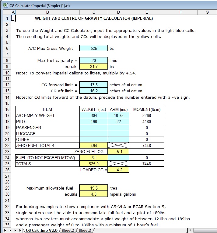
If you download it and open it in XL you can enter the weights you've got on your plane and it will tell you where your CG is for any fuel and pilot weight you enter.
To start filling out the spreadsheet I entered the A/C max gross weight in the box at the top of the form as 525 lbs. Then I entered the max fuel capacity as 20 ltrs, which is approx 4.5 imp gallons, or around 5 US gallons. Then I entered the forward CG limit as 13.5" And I entered the CG aft limit as 16.2"
Then, to get the measurements and weights to enter into the centre table I went to the last W&B calcs I could find for my plane. They were as follows;
So I entered the total i.e. 304 lb into the Weight (lbs) column in the table
To get the ARM (moment arm) in ins, I used the following measurements in inches
Dm (distance from leading edge to main wheels) = 3.625 Dt (distance from leading edge to tail wheel) = 139 Dp (distance from leading edge to centre of pilot's weight) = 22 Dr (distance from leading edge to centre of fuel weight) = -11 (note the negative figure!)
And the following weights in lbs
Wm (weight as measured on main wheels) = 288 Wt (weight as measured at tail wheel) = 16 Wf (weight of max fuel) = 32 Wp (weight of pilot) = 187 (naked or around 190 clothed)
Then used the following formula to get the ARM distance.
Am = (Dm x Wm + Dt x Wt)/Wa
or (( 3.625 x 288 ) + ( 139 x 16 )) / 304
Which works out as 10.75.
I entered this number in the ARM (ins) column and the spreadsheet then calculated that the total Moment arm in (lb.in) was 3268
To get the pilot moment arm I entered my weight of 190 lbs in the Weight (lbs) column, then entered 22 in the ARM (ins) column. This gave a total moment of 4180.
So my zero fuel totals were Weight (lbs) 494, and moment arm 7448
This meant my zero fuel CG was calculated as being 15.1".
Because I'd entered my max fuel as being 20 ltrs earlier, the calculator then said that my fully loaded CG was 14.2", however, the fuel (to not exceed MTOW) box showed 31 lbs, or 19.5 ltrs as being the maximum fuel I could put in the front tank and stay within an MTOW of 525 lbs.
So to stay within MTOW I can't fill the fuel tank, but must take off with it less than full. If on the other hand I raise the MTOW from 525 to 560, and then enter 20 ltrs in the max fuel box, the CG then still shows as 14.2", but now the max fuel weight shows as 32 lbs.
If you go through the same process you can do lots of 'what if's' whereby you can try putting in different numbers to see how they affect the CG.
Thanks Bob, I have one of these spreadsheets , though I didn't use it to figure out the CG in this case. If you know the actual weights on the 3 wheels and the length of the 2 arms, you can do the CG with the free calculator on your cell phone.
Yes, it is useful for "what-if" analysis. Even that has some limitations. For example if I add 4 lbs weight at tail unit, it is difficult to know exactly how much of the weight will come on tail wheel and how much will transfer to the main wheels ( unless I add the extra weight at exactly the tail wheel location.) Even if the weight is a few inches forward of tail wheel, some weight will transfer to main wheels. So for a final determination of precise CG location, one may still need to weigh the plane on its 3 wheels in the configuration you decide to keep. But I agree these spreadsheets are useful.
What I'd do in order to find the moment arm of the 4 lbs is measure from the tail wheel itself to where the weight will be fitted in the rear fuselage. Looking at mine I reckon it's about 12" from where the tail wheel is to where the 4 lbs would be put. So then I add figures into the OTHER boxes on the spreadsheet I showed you above. I'd put the 4 lbs in the WEIGHT (lbs) box and 127 in the ARM (ins) box. That way you've added it as a separate item, so all the other figures remain the same.
So if I were to enter the figures as I've just described into my own spreadsheet then what I'd get out is what's shown below.
Do you know I never thought about that before. I didn't think about the negative figure for the fuel moment arm, but now you mention it, the spreadsheet seems to be ignoring it altogether.
I'll have to do the calcs on paper and include the Df figure and see what difference it makes. Then I may write to the LAA and tell them about the omission and the difference it makes to the correct CG figure.
I guess being able to calculate the moment arm on fuel is fine, but while you're doing the W&B and have everything set up, why not just do an actual weighing with and without fuel in the tank(s)?
What I'd do in order to find the moment arm of the 4 lbs is measure from the tail wheel itself to where the weight will be fitted in the rear fuselage. Looking at mine I reckon it's about 12" from where the tail wheel is to where the 4 lbs would be put. So then I add figures into the OTHER boxes on the spreadsheet I showed you above. I'd put the 4 lbs in the WEIGHT (lbs) box and 127 in the ARM (ins) box. That way you've added it as a separate item, so all the other figures remain the same.
You have a good point. We should treat the added weight as a third arm.
Actually when you add weight in between main and tail wheels, you can also calculate how the added weight distributes between main and tail wheel. This calculation also involves moment arms.
I have attached a sample calculation. Does this check out ?
I'd have thought the best place to put any weight would be on the wooden block in the rear of the fuselage, that the tail wheel spring bolts to. There's room around the top of the bolt to put something in there, and it can't move very easily because it's boxed in on three sides by the flat wooden plate at the back, and the two curved wooden plates, one on either side. So all you need to do is put some form of block in front of the weight to stop it from moving forwards and on to the tail wheel steering arm that is pivoted by the front bolt of the two that hold the tail spring in position. I've attached a photo of my plane with some of the fabric removed so that you can see what I mean, and I've put a red ring around the area behind the mounting bolt for the tail spring so that you can see how much room there is to put any weight. (I had to take the fabric off as I've replaced the wooden block and the upper and lower plates that the tail spring bolts to)
As that's the furthest back the weight can be fitted, it will have the most effect on the CG of the plane in that position. Putting it under the front of the horizontal stabiliser will have quite a lot less effect, as it's almost 2 ft ahead of the tail end of the fuselage. Which means you'll have to add lots more weight at that position to have the same effect as adding much less weight further back.
To put numbers to this, on my plane the distance from the datum to the tail wheel is 139". The tail end of the fuselage is approx 1 ft ahead of that, or 127" from datum. So if I add 1.25 lbs of weight at the tail end of the fuselage, the moment arm figure (lb. in) is 158.75. However, if I add the 1.25 lbs at the front of the horizontal stabiliser, it's now only 103" from the datum, so the moment arm is now only 128.75, a drop of 30 lb/inches.
I am not able to access that location with the fabric in place. Anyways, I will figure out something after a few flights, if I know for sure that I need to retain this weight.
The area at the top (that's underneath the tail feathers) should be open, not covered in fabric, so that you can reach down inside. It even says it on the plans! See the section of drawing 11 that I've cropped. I've ringed the text where it says to cut away the fabric.
You could also put 'bang' panels (round inspection panels) on each side of the tail section, in the fabric to allow you to access it better. See the second pic below to see what a 'bang' panel is. I believe they got the name of bang panels because if fitted on a metal aircraft, you can literally bang them in the middle to make them spring outwards so that you can remove them.
They're very cheap, around £3 or $4 each, so you could afford to put one on each side. Oh, and don't forget to order the round rings that go with the panels. They're less than $1 each, so not expensive.
The idea is that you glue the ring onto the fabric, and once the glue is dry, you cut out the circle within the ring. Then you can fit the panel by springing the two strips of spring steel away from the plate and pushing them behind the ring, then centring the panel.
See the photo below of one of my ailerons, that I had to put a bang panel in because the bolts that hold the horn had come loose. It only took a few minutes to fit the panel, and it made all the difference. I was able to get in and tighten the bolts easily with the panel being there because I could remove it in seconds, and once the bolts were tight I could refit it again in seconds.


 Logged


