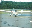
The NIson Easy arrived safely in KS tuesday evening, thanks to Greg Doe for bringing her out here!
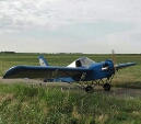
At first glance her simillarities to the minimax line end at her looks. With a semi monocoque ply fuselage and sheeted wings with a single strut. I will go into greater detail on her construction methods a bit later but for now i will say the build has been greatly simplified vs the standard 1100 and i would bet she could be built in under half the time.
Other differences of note are the airfoil shape, aileron design, and tail design and construction.
From what I have been told, the original was lost in a takeoff accident after less than 3 hours flight time and the second prototype was constructed. Construction was not completed before Tennessee Engineering and Manufscturings bankruptcy and the design was not sold to JDT. It remained in Skip's possession after the sale and was completed to the point of being 95% ready to fly. It still needs it rudder and tailwheel cables completed and rigged and has some hangar rash that it has incurred that needs repaired.
I must say, I am looking forward to being only the 2nd person to fly a NIson Easy.
Chris
Remember, in aviation death sentences are administered by the laws of physics, not the FAA.
I wonder if the current TEAM Mini-Max owner would be interested in buying the design and bringing it to market. I think it's a very interesting design.
It is, if it performs well, I may try and build a duplicate as it seems like a very simple build. If that works i might draw up a set of plans. From what ive been told the originals were built off rough sketches and no plans existed for it.
Chris
Remember, in aviation death sentences are administered by the laws of physics, not the FAA.
The airfoil still looks like a Clark Y - is there much difference? Presumably the wing structure is different to be stiff enough with a single strut. How thick is the fuselage skin? Clever trick to make a monocoque lighter: usually dacron is the lightest covering, especially over the Max's minimal fuse structure.
Which engine is fitted?
I'll be very interested to hear more of construction techniques & flight handling.
The speculative side of me can't help but ask if it's plywood panels only with fiberglass reinforcement tapes on the corners towards the ends, and 4 longerons in the mid section bonded to the "shell"?
From what I have been told, the original was lost in a takeoff accident after less than 3 hours flight time and the second prototype was constructed. Construction was not completed before TEAMs bankruptcy and the design was not sold to JDT. It remained in Skip's possession after the sale and was completed to the point of being 95% ready to fly. It still needs it rudder and tailwheel cables completed and rigged and has some hangar rash that it has incurred that needs repaired.
I must say, I am looking forward to being only the 2nd person to fly a NIson Easy, Wayne Ison's last aircraft design.
I got out to the airport yesterday evening to continue working on the NIson Easy. The first item on the agenda is installing a propper tail wheel spring /wheel and rigging cables. Along with repairing a bit of damage to the fuselage caused by the previous setup (an aluminum rod affair). After that I have the following items to address:
1.Reinforce horizontal stab fwd attach points. 2. Remove wings and replace fwd attach tang on left wing(double drilled). 3. Repair cracked gusset and add additional gussets to rear spar carry through. 4. Remove seat and inspect/make any necessary tepairs to the fwd spar carry through. 5. Reinstall wings and repair hangar rash to wing skin.
I am un decided on wheather i am happy with the gear attachment method. Currently there is a short 6" piece of piano hinge at the rear and a single aluminum bracket at the front.
I cut away a damaged portion of the wing skin and got my first look inside the wings. Construction seems very skypup like! Foam everywhere! The spar caps appear to be 1/2" douglas fir with a foam web and foam ribs, and skinned with 3/32 ply. The only fabric covering on this plane is on the tail, everything else is sheeted. The design logic appears to have been, what is the easiest and simplest way to build an airplane! I think team got pretty close with this one!
Below are a few pics of the wing interior, ill be going back out this evening to finish installing the tailwheel spring and see if there is any life in the motor.
Got some more work done monday evening, the tailwheel spring is now of standard minimax configuration. As soon as i have the horizontal stab attach points reinforced a bit the tail will be ready to reinstall. I think i am going to take the easy way out and route the tailwheel steering cables externally. The Nison Easy was previously configured as tri gear and it still has the external nose gear steering arms protruding from the belly which will make cable routing and hookup a snap!
Another Wyne Ison design was the PDQ 2. A very minimal aircraft.I dont know if any were actually built.Recently Free Dwgs were posted on Facebook group (Aviation Plans).If anyone is interested can have a look.
NIson Easy Update: I finished beefing up the horizontal stab attach points by installing a vertical between the top and bottom longerons on each side and gusseting them to the little ply blocks that served as the hardpoints for the L brackets. teally made the whole thing a lot more rigid.
I figured my next project would be to get the seat out and inspect the fwd spar carry thru, something didnt seem right as the seat moved and the fuselage sides deformed when you applied pressure to the wings. What i found was a little shocking and i have no doubt that this airplane would have killed me had i tried to fly it.
It has NO spar carry thru structure! the wing attach points are literally bolted to the 1/4 ply seat bottom! literally the onlything keeping the wings from lifting right off of the fuselage is the weight of your butt on the seat and the only thing keeping the attach points from pulling out is the shear strength of the 1/4 inch ply seat bottom.
So this project is going to be on hold for a while, im going to pull the hirth for use on my 1100 while i thoroughly search the Nison Easy for other poorly engineered areas and ponder what to do next.
Wow! Didn't this plane fly at least once? I hope you can find some history to reveal whether this is how it was, or if it got modified somewhere along the line. Pretty scary.
Is there any indication that the wing root rib was designed to distribute the compressive force over the outside of the fuselage? It appears that the brackets were fitted to the vertical frame member to transfer any vertical load, and if the struts were properly located and pin joints in theory the carry through should only be seeing compressive loads. Perhaps if properly distributed over the length of the seat (which is reinforced from buckling underneath with frames and above by pilot weight) through the skin if it was a tight fit...just thinking outside the box, I doubt an experienced designer would have made that big of a mistake, there might be more to it than meets the eye. If only the original design calculations (if any) could be found it might shed some light on it.
The lift is reacted by the strut. It is a "lift" strut. There is no shear at the wing root. Stilson is probably right, the compression is reacted by the cross members under the seat.
The verticals you see in the pic dont contact the attach fittings, they are just bolted thru the fuselage skin to act as a stiffener and keep the skin from flexing too much.
With the wings installed you could walk up to the leading edge and lift it from the bottom, the entire seat would move up until the wing attach fitting contacted the bottom of the vertical (about 3/16 of an inch. If you applied a foward or aft load to the wingtip you could feel the wing move and see the fuselage sides deform under load. The 1/8th ply skin on the right side has a crack about 7" long just above the seat that likely resulted from this motion during a taxi test.
You cant just bolt the wing spars to the seat, you need to have a good solid carry thru to transfer the load to the fuselage structure.
Remember, in aviation death sentences are administered by the laws of physics, not the FAA.
Without doing a structural analysis of the craft I would in no way say that it is safe/appropriate to fly it, but I will say again that there may be more to the structural design than initially meets the eye. Lifting on the leading edge Is not an accurate representation of the actual forces acting on the wing in flight. Look at a paraglider, an entire "structure" under tension. Stress vectors are not alway intuitive 😉. With the experience background he had i again doubt he would have made that big of a goof up...
What im saying is i dont believe this plane was ever completely finished. I suspect that this wing attsch method was meant to be temporary. The structure has already failed under taxi loads resulting in damage to the airframe. If it cant hold up to taxi testing it shouldnt fly, no matter how it was engineered. You would agree right?
Chris
Remember, in aviation death sentences are administered by the laws of physics, not the FAA.
I concur with Stilson. When designing light and simple, the designer may decide to ignore handling loads. This airplane appears to have the lift strut at the center of the span-wise loading like the Minimax and Himax, then there is no vertical lift load at the wing root. With no angled rear strut, there is less compression in the forward spar. The airfoil appears similar to the Minimax so I would assume a similar moment coefficient. Then the wing torque box could apply a torque to the fuselage, a down force at the front attachment, up at the rear. But the front attachment might be very near the quarter-chord point and thus all the wing torque is carried into the fuselage by the rear attachment. But handling and pilot protection among others are valid design concerns and should be addressed. Drag and anti-drag forces have to be picked up as well. Is there a way to put an AL channel under the front of the seat as Mullacharjak suggested? And a wood member would likely suffice for a rear carry-through.
The photo of the interior of the wing made me nervous; I saw no provisions to carry the shear loads (open spaces, no shear web) and it appeared to rely on the foam ribs to carry the vertical loads between the spars. It almost looks like a scaled up R/C model structure.


 Logged