|
|
 Keith103 Keith103 |
| December 10, 2019, 5:49pm |
|
 Ace Ace Posts: 632
Time Online: 13 days 6 hours 31 minutes
|
Referencing discussions quoted below: I would be willing to pay for an electronic version of the stress analysis of the Max designs, the 103 in particular. Just in case someone has a copy to sell, or, if David Cooper has plans to make this available. I am assuming these are not easy to find. Holiday greetings to the Max community !
Right. The drag/anti-drag truss in the wing with its geometry and loading, is a Pratt truss. A feature of the Pratt truss is that the diagonal members are loaded in tension. The TEAM stress report says the root diagonal has a tensile force of 831lbs in the design case and a safety factor of 1.99 so the fixtures of the diagonal should be able to resist 1654lbs. System3 quotes a tensile strength for T88 of 7000psi and a lap-shear strength of 1800psi. The TEAM report states the shear strength of western white pine is 920psi so the glue is stronger. In the original Minimax wing, the diagonal attachment is a lap joint at both ends and the aft connection has a slightly smaller area, 1.8 in2, so it is the weak link. Then we have:
1.8in2 x 920 psi = 1656lbs.
With the wing tank mod, the forward joint is still a lap joint so the joint has the same strength plus any extra supplied by the butted joint area. It is stronger than originally designed. However, the aft attachment is now butted to the spar cap and the joint is dependent on the tensile strength of the spruce spar cap (170 psi, ANC-18 ) plus the shear strength provided by the ply gusset. We have:
2in2 x 170 psi + 1.8in2 x 990 psi x .5 = 1231 lbs
|
|
 Logged Logged |
|
|
|
|
| Bob Daly |
| December 10, 2019, 8:51pm |
|
Ace
Posts: 888
Time Online: 45 days 22 hours 25 minutes
|
I have a pdf but it exceeds the attachment size allotment. It doesn't appear to be copyrighted. I'd be willing to send you a copy but I'd need an email address. |
|
| Logged |
|
|
|
|
| Keith103 |
| December 11, 2019, 6:48am |
|
Ace
Posts: 632
Time Online: 13 days 6 hours 31 minutes
|
Bob, That is very nice of you.
I have PM'd my email Id to you.
Many thanks. |
|
| Logged |
|
|
|
|
| toliver66 |
| December 11, 2019, 4:34pm |
|
Ace
Posts: 208
Time Online: 3 days 7 hours 3 minutes
|
|
|
|
|
|
| timyandow |
| December 11, 2019, 5:14pm |
|
 Fledgling Member  Posts: 23
Time Online: 1 days 28 minutes
|
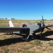
Thanks for posting this. I have been curious what airfoil these planes used but couldn't find it anywhere. - (modified NACA 4414) |
|
|
|
|
|
| radfordc |
| December 11, 2019, 8:06pm |
|
 Ace AcePosts: 1,836
Time Online: 18 days 1 hours
|
Thanks for posting this. I have been curious what airfoil these planes used but couldn't find it anywhere. - (modified NACA 4414)
I was told that Wayne called his airfoil the "Ison 12"....said he drew it around the edge of a size 12 shoe. |
|
|
|
|
|
| Tom |
| December 11, 2019, 9:03pm |
|
Ace
Posts: 744
Time Online: 16 days 10 hours 21 minutes
|
Radfordc:
The thing about the "shoe" is very old. I first heard it said of Bernard Pietenpol. I don't know if it was true in his case in which the section actually has a leading edge that could be an outline of the toe of the shoe, but I know a fair amount about airfoils and the leading edge of the MiniMax airfoil section looks perfectly conventional to me and nothing like a shoe. It makes a good story but I'm pretty sure it is one of those myths which grow up.
Tom |
|
|
|
|
|
| Bob Daly |
| December 21, 2019, 12:07am |
|
Ace
Posts: 888
Time Online: 45 days 22 hours 25 minutes
|
So, lets unpack this report and put some math behind the numbers starting with the flight envelope.
The report says the maximum lift is: 1.05 x gross wt x load factor then 1.05 x 560 x 4.4 = 2587 lbs
The 1.05 factor accounts for the down load on the tail.
Then, using the formula for lift L = 1/2 ρ V2 S CL we can find VS and VA
560 = .5 x .002378 x V2 x 112.5 x 1.5 then VS = 52.8 ft/sec or 36 mph
And
VA = (4.984(2587))1/2 = 113.6 ft/sec or 77.5 mph (!)
But FAR Part 103 says to use a CL of 2.0 for a full-span flapped wing so (1.5/2)1/2 x 77.5 = 67 mph |
|
| Logged |
|
|
|
|
| mullacharjak |
| December 21, 2019, 9:23am |
|
 Ace AcePosts: 281
Time Online: 3 days 21 hours 12 minutes
|
77.5mph (!) Because it looks higher ?
67 mph looks about right.The crude formula for Va= 2x Vs also seems just about right. I was curious how the Vne relates to all of this?
|
|
|
|
|
|
| Bob Daly |
| December 21, 2019, 5:05pm |
|
Ace
Posts: 888
Time Online: 45 days 22 hours 25 minutes
|
77.5mph (!) Because it looks higher ?
67 mph looks about right.The crude formula for Va= 2x Vs also seems just about right. I was curious how the Vne relates to all of this?
Because the report lists V a as 67 mph but the airspeed for design purposes should be determined using the unflapped wing maximum C L. From figure A-1, V A looks like about 75 mph. V ne is usually a safe fraction (90%) of the dive speed and the dive speed is demonstrated by flight testing. So we might guess that Colley dove a Minimax to 111 mph establishing the V ne at 100 mph. The wing torsion at point A is: M w = C Mc/4 x chord x wing area x .5 x ρ x V 2 M w = -.1 x 4.5 x 112.5 x .5 x .002378 x 113.6 2 = -777 ft/lbs |
|
| Logged |
|
|
|
|
| Bob Daly |
| December 21, 2019, 7:11pm |
|
Ace
Posts: 888
Time Online: 45 days 22 hours 25 minutes
|
The formula for drag is:
D = .5 ρ V2 CD Areawing and
CD = CDzero lift + CL2 / π (Aspect Ratio) e where e is .7 for a rectangular wing
then
Dwing = .5 x .002378 x 113.62 x (.01 + 1.52/12.2) x 112.5 = 335 lbs |
|
| Logged |
|
|
|
|
| Bob Daly |
| December 28, 2019, 6:21pm |
|
Ace
Posts: 888
Time Online: 45 days 22 hours 25 minutes
|
We can expect the fuselage to carry its share of the loads which are about 110% of the running span load times the fuselage width, then load on one wing panel expressed as a factor is:
(1 - 1.1 x 22"/300")/2 = 0.46
To account for wing weight and inertia relief we have:
Vertical load = Liftpanel - load factor x wing weight = 2587 lbs x 0.46 - 4.4 x 35 lbs = 1036 lbs
Horizontal load = load factor x wing weight - Dragpanel , where the load factor is drag/gross weight then,
335 lbs/560 lbs x 35 lbs - 335 lbs x 0.46 = -133 lbs (rearward is negative by convention) |
|
| Logged |
|
|
|
|
| Bob Daly |
| December 28, 2019, 6:45pm |
|
Ace
Posts: 888
Time Online: 45 days 22 hours 25 minutes
|
If the slope of the lift curve is .1/° and the wing incidence is 2° then the angle of attack relative to the fuselage is:
Alphafuselage = CL/.1 + 2 = 1.5/.1 + 2 = 17°
And the normal and chordwise loads are:
N = V cos A - H sin A or 1036cos17 - (-133)sin17 = 1030 lbs
C = V sin A + H cos A or 1036sin17 + (-133)cos17 = 176 lbs (forward!)
|
|
| Logged |
|
|
|
|
| Bob Daly |
|
Ace
Posts: 888
Time Online: 45 days 22 hours 25 minutes
|
Now we'll take the normal and wing moment loadings into the spars. From the picture we have the simultaneous equations:
ΣFy = 0 , Vf + Vr = 1030 lbs
ΣMc/4 = 0 , 1.86 Vr = 0.49 Vf + 357 ft-lbs
And Vf = 656 lbs
Vr = 363 lbs
|
|
| Logged |
|
|
|
|
| Bob Daly |
|
Ace
Posts: 888
Time Online: 45 days 22 hours 25 minutes
|
For the Schrenk approximation, Colley used 80 segments of 1.875". That makes sense because the semi-span is 150" and the rib bays are 15" so there are 8 segments between each rib. One could probably get reasonable results with 40 or even 20 segments. We need Schrenk to distribute the normal loads over the span and analyze the spars for bending and shear and to distribute the chord load to analyze the drag truss. The idea is to calculate load coefficients for each segment and apply those to the total load to determine the segment loads. Then the stress at any point is the sum of the segment loads to that point. The area of an ellipse is given by: S = π a b where a and b are the major and minor semi-axes. Then a half-ellipse has an area, S = π a b/2 and b = 2S/ πa The equation of an ellipse is x 2/a 2 + y 2/b 2 = 1, then y = b ( 1 - x 2/a 2) .5 but x 2/a 2 = (x/a) 2 Then for an elliptical wing, the chord, c, at some point, x, along the half-span is: c = 2S ( 1 - (x/a) 2) .5 / π a For the Minimax, 2S/ πa = 225/(3.14 x 12.5) = 5.73 ft or 68.75 in At x = 0 the chord is 5.73 feet. The Minimax chord is 4.5 feet so the Schrenk chord at the root is the average, 5.115 feet. Expressed as a % of the actual chord, 5.115/4.5 = 1.1367. Divided by the number of segments gives us a load coefficient, 1.1367/80 = 0.0142 A spreadsheet helps to calculate the load coefficients for each 1.875" segment. Another argument for fewer segments  |
|
| Logged |
|
|
|
|
| Bob Daly |
|
Ace
Posts: 888
Time Online: 45 days 22 hours 25 minutes
|
Here is the fully developed Schrenk approximation. Note that loads on the wing begin at station 7 because station 6 ends at 11.25" from the 22" wide fuselage centerline, another reason for choosing 1.875" as the segment width. The columns are calculated as follows:
(2) = (1) x 150/80
(3) = (2)/150
(4) = 18/π x (1 - (3)2).5
(5) = ((4) + 4.5)/2
(6) = [( (5) + (5)prior)/2]/4.5
(7) = (6)/80
(8) = (7) x (2587-4.4x70)/2
(9) = (7) x (335-0.5x70)/2
(10) = (8) x cos17 + (9) x sin17
(11) = (8) x sin17 - (9) x cos17
(12) = 388.5 x (7)
(13) = (10) - (14)
(14) = [0.49 x (10) + (12)]/2.35
|
|
| Logged |
|
|
|
|
| Bob Daly |
|
Ace
Posts: 888
Time Online: 45 days 22 hours 25 minutes
|
The segment totals are slightly higher than the previous estimates so we'll use them going forward:
|
|
| Logged |
|
|
|
|
| Bob Daly |
|
Ace
Posts: 888
Time Online: 45 days 22 hours 25 minutes
|
If we take the segment spar loads in columns (13) and (14) and multiply by their distances from the strut attachment point we can then sum the resulting segment moments to get 931 ft-lbs clockwise on the inboard section and 937.4 ft-lbs counter-clockwise on the outboard section for the main spar.
Then given ΣMstrut = 0 and ΣFy = 0 we get the vertical strut and root reactions:
Rstrut + Rroot = 669 lbs
937.4 - 931 = Rroot x 5.33 and Rroot = (937.4 - 931)/5.33 = 1.2 lbs up! so Rstrut = 670 lbs down
A trivial adjustment that Colley may have dispensed with. |
|
| Logged |
|
|
|
|
| Bob Daly |
|
Ace
Posts: 888
Time Online: 45 days 22 hours 25 minutes
|
Here is the Lift truss geometry with dimensions in inches:
|
|
| Logged |
|
|
|
|
| Bob Daly |
|
Ace
Posts: 888
Time Online: 45 days 22 hours 25 minutes
|
Using the values for the strut attachment point reactions we can calculate the strut loads. The loads in the spars and struts will be proportional to the lengths of the sides of the triangles formed. Then:
Loadfront strut = 670 lbs x 55/29 = 1271 lbs
Loadrear strut = 367 lbs x 62/28 = 811 lbs
Loadmain spar = 670 lbs x 47/29 = 1085 lbs
Loadrear spar = 367 lbs x 47/28 = 616 lbs
Likewise, the anti-drag load imposed on the wing by the struts is calculated:
( 1271 x 2/55 ) + ( 811 x 29/62 ) = 426 lbs |
|
| Logged |
|
|
|
|
| Bob Daly |
| January 14, 2020, 11:04pm |
|
Ace
Posts: 888
Time Online: 45 days 22 hours 25 minutes
|
With this result:
Loadmain spar = 670 lbs x 47/29 = 1085 lbs
I believe there is an error in Figure C-4 of the stress report. If 47/29 is rounded to 1.6 then the result is 1072 lbs. Figure C-4 shows the load as a strut load though it is labeled "front spar load = 1072 lbs". The error is repeated near the bottom of the figure.
|
|
| Logged |
|
|
|
|
| Bob Daly |
|
Ace
Posts: 888
Time Online: 45 days 22 hours 25 minutes
|
Plowing ahead we analyze the drag truss (in red). The chordwise segment loads are summed from the tip to points midway between the compression ribs then those distributed loads are represented as point loads at the compression ribs. At rib F, the strut anti-drag loads come in. Root reactions to be determined are shown.
|
|
| Logged |
|
|
|
|
| Bob Daly |
| January 16, 2020, 10:57pm |
|
Ace
Posts: 888
Time Online: 45 days 22 hours 25 minutes
|
The internal compressive load on compression rib H is 34 lbs. Since the outer spar sections can't be allowed to bend, the external 34 lbs must be reacted by tension in diagonal D. The tension in D is 34 lbs x 40/28 = 49 lbs. The tension in D pulls compression rib G forward with a force, 28/40 x 49 = 34 lbs and the total compression on G is 34 + 37 = 71 lbs. Then we have the internal forces:
H = 34 lbs
D = 34(40/28) = 49 lbs
G = 49(28/40)+37 = 71 lbs
C = 71(40/28) = 102 lbs
F = 71 + 466 = 537 lbs
B = 537(40/28) = 768 lbs
E = 537 + 42 = 579 lbs
A = 579(40/28) = 828 lbs
With the diagonals in tension and the compression ribs in compression which makes this a Pratt truss. Now if we add up all the diagonal loads and multiply by 30/40 or 0.75 we will get the root reactions, 1310 lbs. The root reactions are a couple and would spin the wing backward except they are reacting the anti-drag forces pulling the wing forward.
Knowing the spar loads(compressive) and the drag truss reactions (alternating compressive and tensile) we can calculate the fuselage carry-through loads:
Main spar carry-through = 1310 lbs + 1085 lbs = 2,395 lbs compressive
Rear spar carry-through = 1310 lbs - 616 lbs = 694 lbs tensile |
|
| Logged |
|
|
|
|
| radfordc |
|
Ace
Posts: 1,836
Time Online: 18 days 1 hours
|
Bob, I stand in awe... Thanks. |
|
|
|
|
|
| Dick Rake |
|
 Home phone 602-999-3715/Mini-max with Hirth 2704 AcePosts: 755
Time Online: 40 days 13 hours 26 minutes
|
Bob,
I was going to tell you that I was in awe about your stress analysis but I didn't know how to spell awe so I had to wait on Charlie's post to get the correct spelling. I wanted to be first but being a dummy does create some limitations. |
|
|
|
|
|
| Bob Daly |
|
Ace
Posts: 888
Time Online: 45 days 22 hours 25 minutes
|
Thanks guys. The real credit goes to Richard Hiscocks and his book "Design of Light Aircraft". He designed the de Havilland Beaver. His book describes the design process along with an example. It is easy to follow and confirms that the calculations are fairly simple using established formulas, arithmetic and some trigonometry. I merely applied the method to the Minimax.
At this point, we have the loads for the wing and its reactions for point A of the flight envelope. They represent a design case for the main spar and strut and the drag truss components. The same process could be done for the other corners of the envelope. |
|
| Logged |
|
|
|
|
| ITman496 |
|
 Ace AcePosts: 411
Time Online: 1 days 23 hours 31 minutes
|
This was a good read and I learned a lot!
Is there an easy way to test the structure of an already built by another person minimax non-destructively to make sure it was made up to snuff? My wings are already covered and I have no desire to re-do that if I can help it. |
|
|
|
|
|
| radfordc |
|
Ace
Posts: 1,836
Time Online: 18 days 1 hours
|
A non-destructive load test can be done at a loading below the design limit. For instance, you could test your wings to 3g's. This is a load that you might experience in actual use. If your wings show no ill effects at 3g's you will at least know that they should withstand normal use. If a problem does show up in a 3g test you wouldn't want to ever fly with them anyway. |
|
|
|
|
|
| ITman496 |
| January 22, 2020, 10:58pm |
|
Ace
Posts: 411
Time Online: 1 days 23 hours 31 minutes
|
How would I apply the load to them? Flip the airframe upside down, and pile sandbags on the underside of the wings with plywood and foam to distribute the load? |
|
|
|
|
|
| Bob Daly |
|
Ace
Posts: 888
Time Online: 45 days 22 hours 25 minutes
|
How would I apply the load to them? Flip the airframe upside down, and pile sandbags on the underside of the wings with plywood and foam to distribute the load?
Essentially. The stress report describes this in the appendix. I don't think a test with covered wings is a good idea however. I'd want to observe the structure as the loading progresses. Did you look the wing structure over before covering? What is the overall workmanship like? |
|
| Logged |
|
|
|
|
|


