ULB, Thanks. Yes I had seen this report some time back, but at that time as I was in a different phase of building, did not give much thought to the bracket in question.
Come to think of it, why is the steel cable going all the way around the elevator teleflex cable ?? If the cable is just for anchoring the seat harness, why not just loop it through those two holes, but avoid routing it around the elevator cable. Am I missing something ?
Thanks for the pictures. By adding the thimble, you have eliminated the sharp 90 degree corner contacting the cable. I notice you also avoided looping it around the teleflex cable.
I have simply chamfered the edges of the two slots through which the cable passes. Hopefully that will prevent the cable from being cut by the sharp 90 degree edge. Also I will try to pass the cable above the teleflex cable without fencing it. Otherwise with each tug on the seat belt , for example from braking or whatever other reason, the teleflex is needlessly getting tugged / crimped. Even allowing for the fact that, at that location, the teleflex cable has the metal sleeve and is more sturdy.
Possibly, there may be some other unexplained reason why the cable is routed around the teleflex cable. Any thoughts on this from other members will be appreciated.
Hi Lynn, Since you brought up the issue of the seat back's position in another thread, I clarify that subsequent to my question raised in reply # 101 above, I did find the following drawing in the construction manual for Max 103. But it was located on a different page. So these two images below are conflicting seat positions given in the same construction manual. I concluded this is a good thing because it gives me the discretion to move my seat fore and aft by about 2 inches, and this may come in handy at time of weight and balance. I am only 5-7 , so even with seat bottom / back moved 2 inches forward, I do not feel cramped. However with the forward position I may need to provide some support for the seat back, as the top of the seat back will also move forward, and will be 2 inches ahead of station 4. The eventual positioning may have to wait till W&B stage.
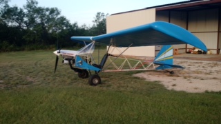
Kieth looks like your build is going great. After watching your video I have a few comments that you might already looked at. The forward wing pins will need to be anchored to the wood uprights on the fuselage sides because they will vibrate out...ask me how I know. A fiberglass foot insert will make getting in a lot easier. Team makes a great fiberglass cowl which really streamlines the nose and looks great. Keep up the great work.
WOW! Did that ever bring back a flood of memories of the day I had mine together like that for the first time. Looks great! I'll bet you had your neighbors talking.
texasbuzzard's suggestion on securing the wing pins is good. I went a bit different direction and used drilled AN-4 bolts, castellated nuts and "hairpins" instead of the 4130 rod pins. The bolts, and especially installing the hairpins" are more "fiddly" to install and remove but certainly secure.
Have fun continuing with your construction. BTW, it looks like you live in a nice neighborhood.
Monte, Lynn, and Ricardo, thanks for your comments, feedback and encouragement.
By assembling the wings, one at a time, inside a closed garage, I had gambled a bit, because there was a possibility that both wings may not line up symmetrically when joined together, at the same time. Luckily it came out acceptable, and both wings looked kind of symmetrical when viewed from the front. However I did notice that the rear of the front spar caps were slightly tilted backwards from the front Aluminum channel that holds the front spar pins. Just a little bit. However that will get covered by the fabric. I have not yet fitted the two small aluminum bushings / sleeves into which the rear spar pins insert, so I have a bit of wiggle room to make the wings line up in a fore-and aft direction by adjusting the positioning of the rear spar pins' final placement.
We had pretty strong winds last week, then snow on Saturday, and snow again today ( Tuesday ). So I got a few hours on Monday, just enough to roll the thing out and do my alignment check of the wings. The spar pins need replacement with 4130 steel, which I am awaiting to ship from ACS. They are on back order. Monte, yes, I will secure the spar pins, so they don't slide and fall off.
Bruce, Cdlwingnut, and Jeff, thanks for your comments. Appreciated. Monte, I have not decided on the engine, except that it will likely be a light sub-30-hp true ultralight engine. Rotax 277, Kawasaki 340 and Hirth F33 are on my mind. I have read good reviews about Kawasaki 340. Wondering if anyone uses it on a Max.
During my decision making on what to build I was looking at the Simplex Aero Zing. If you search Zing Ultralight on YouTube The designer talks about the Kawasaki 340. He said it ran to hot when set up for free air, he switched to liquid cooled and liked it much better. Your build looks great! I can't wait to start on mine.
After hooking up the control cables to all 3 control surfaces, I noticed that the elevators are moving freely, but there is some amount of stiffness in the aileron movement, though the ailerons are able to swing through their full deflection range. Just that little more force is required to move the ailerons than the elevator.
With the teleflex cable disconnected, the ailerons are able to move freely when moved manually, meaning the resistance to free movement is not due to the hinges or caused by the aileron itself, but due to some issue with the way the aileron control cable is hooked up. I was wondering if this is considered normal for this type of control set up ?
Keith mine had some resistance due to the 90 deg radius the cables make from the horn to the stick. They probable will ease up a little after they wear in but won’t be free as the elevator.
This is a link to the video of the empennage. I would welcome suggestions / corrections required if any, especially where you feel something is not right / safe. Thanks
I bought the covering iron ( pic below ) from Aircraft Spruce &S. Many other builders must have used the same or a similar iron I guess for covering. I used this iron on setting 2 on some test frames covered with Ceconite, and it worked well. I know it was not too hot at setting 2, because it took three to four swipes on each fabric frame to make it reasonably drum-tight. Do I need to buy a thermometer separately or can I use this TLAR setting ? Thanks for your opinion and suggestions.
There are many others that are far more qualified than me to discuss tightening fabric, but I won't let that stop me from offering my opinion.
I think it would be money well spent to buy an inexpensive infrared heat gun. Here's the first one that caught my eye, and they're available many places. https://www.homedepot.com/p/General-Tools-Mini-Infrared-Thermometer-IRT205/303305337 I don't know just how accurate they are, but some simple things could be done, like heating a iron skillet in the oven to say 250 degrees and seeing what the gun says, to check their accuracy and work accordingly.
I used an old household iron that I borrowed from an older gentleman in our EAA chapter. I found it to have a large temp range from off to on and off again. I was constantly checking where it was in the range to try to do the shrinking consistently and in steps.
I think there is some sort of heat tape than can be used to determine the temp of an iron, but I have never used any.
I think it would be money well spent to buy an inexpensive infrared heat gun. Here's the first one that caught my eye, and they're available many places. https://www.homedepot.com/p/General-Tools-Mini-Infrared-Thermometer-IRT205/303305337 I don't know just how accurate they are, but some simple things could be done, like heating a iron skillet in the oven to say 250 degrees and seeing what the gun says, to check their accuracy and work accordingly. Lynn
Lynn, Your reply is helpful. Thanks.
An ancillary question, which was lurking, but which I forgot to ask was, what sort of probe measures the temp of a flat hot plate like an iron. Infra red sounds like an appropriate one.
I was thinking of buying the engine shown in picture below, mated to a 3 blade composite 59 inch prop. The question I have is, whether this set-up will fit on the Max, as-is. My build has an engine-bed made to seat the Rotax 277. If possible I would like to use the existing engine bed without making alterations to the front end of the fuselage.
The Kawasaki dealer says it will work Ok and top of engine will be about 9 inches above fuselage top longeron ( or about 15 inches upwards from the engine bed on the Max). if I move the engine bed 6 inches lower than existing position, then it will improve forward visibility, but it will also require an up-redrive for keeping thrust line at the original intended design. The up-drive sometimes has cooling issues and is less preferred than the down re-drive.
I have seen picture of another Max on this board, ( probably Dick Rake ) which has the Kawasaki engine fitted neatly inside the cowl. But the engine is inverted, which also I would like to avoid.
I saw this picture in the archives. it is a Kawasaki 440 mounted inverted on a Max. The 340 and 440 are same external size, just the displacement is different.
Home phone 602-999-3715/Mini-max with Hirth 2704 Ace
Posts: 755
Time Online: 40 days 13 hours 26 minutes
Thats a picture of my Kawasaki 440 I had in 1994 when I first built the airplane. The only problem I had with the inverted install was after a few days it would oil fowl the plugs but that was with a single points ignition. I think a CDI would create a better spark and the problem might not have been so troublesome. The picture doesn't show it but the engine was fan cooled and I had installed vertical baffling that divided the engine to have a left half and a right half. The inlet on the front of the cowl was on the left side and all air going in was trapped by the baffling so that it had to go to the rear of the engine where the fan inlet was. The hot fan air exited the engine shroud on the right side and drawn out the bottom of the cowl on the right side. The cooling worked well. My Hirth 2704 that I have now is mounted inverted also but with dual CDI ignition I can usually start with one pull even if its been a few months from the last run. If It was my airplane I would see if I could get engine converted to fan cooled and mount the engine and reduction unit both upright. If thats not doable you might be able make a custom designed air-cooled inlet shroud that would have the inlet clear the large pulley. On my Hirth I went air cooled to save some weight and then built a shroud to fit my cowl, but with my engine inverted and the gearbox upright I didn't have the clearance issues you have. Here's a few pictures of my current install.
Thats a picture of my Kawasaki 440 I had in 1994 when I first built the airplane. The only problem I had with the inverted install was after a few days it would oil fowl the plugs but that was with a single points ignition. I think a CDI would create a better spark and the problem might not have been so troublesome.
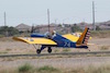
Dick, Thanks much for the information. Very helpful. Since you mentioned about the cooling fan, I was advised to buy an engine with free air cooling, as the direction of fan's airflow ( back to front ) is usually fighting the prop wash, and hence that arrangement is not very efficient, according to them. They also sent me a picture (below) of a Himax fitted with a Kawasaki 340 with the up-redrive, where cooling fan's efficiency may be questionable. Of course, your arrangement of isolating / re-directing the fan's output airflow to the bottom should solve that issue. The engine they are offering to me works well with free air cooling and it also has modified larger fins for the rear cyl, and I think a small scoop on top of the first cylinder for the rear cylinder to get its fair share of ram air for cooling.
Thanks for the heads up on the need for CDI ignition.
Bought this thermometer locally from Lowe's. ($ 20.00 + tax)
Just be a cautious with this approach and be sure to calibrate for the emissivity of the iron surface. The sensor sees thermal power (not temperature). Thermal power varies with surface condition (emissivity) for a given temperature (combination of temp and condition).
Spruce also makes a nice magnetic dial indicator you can also use check your iron that works real well. Temp is critical as an over temp can start to buckle the airframe components.


 Logged